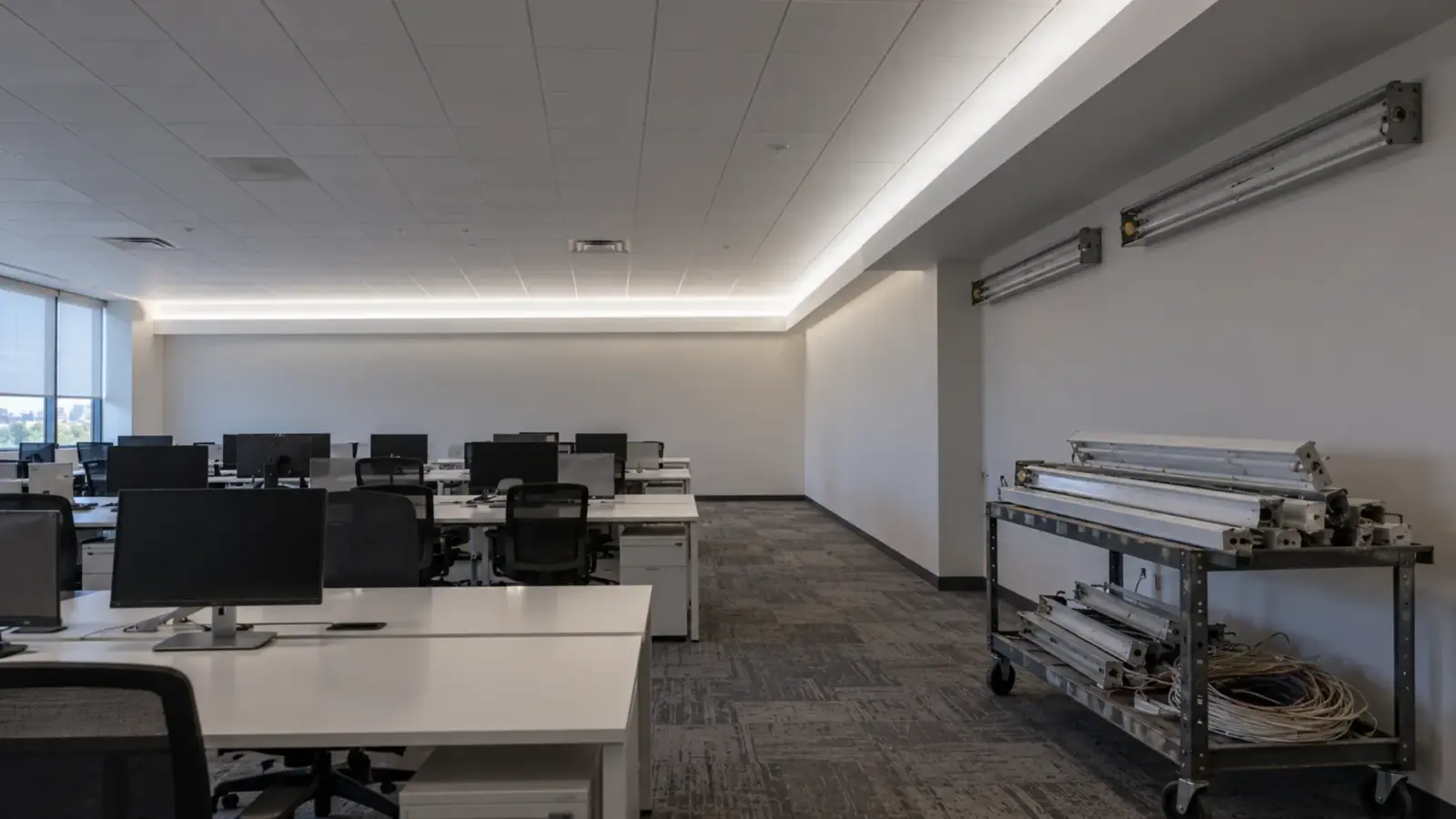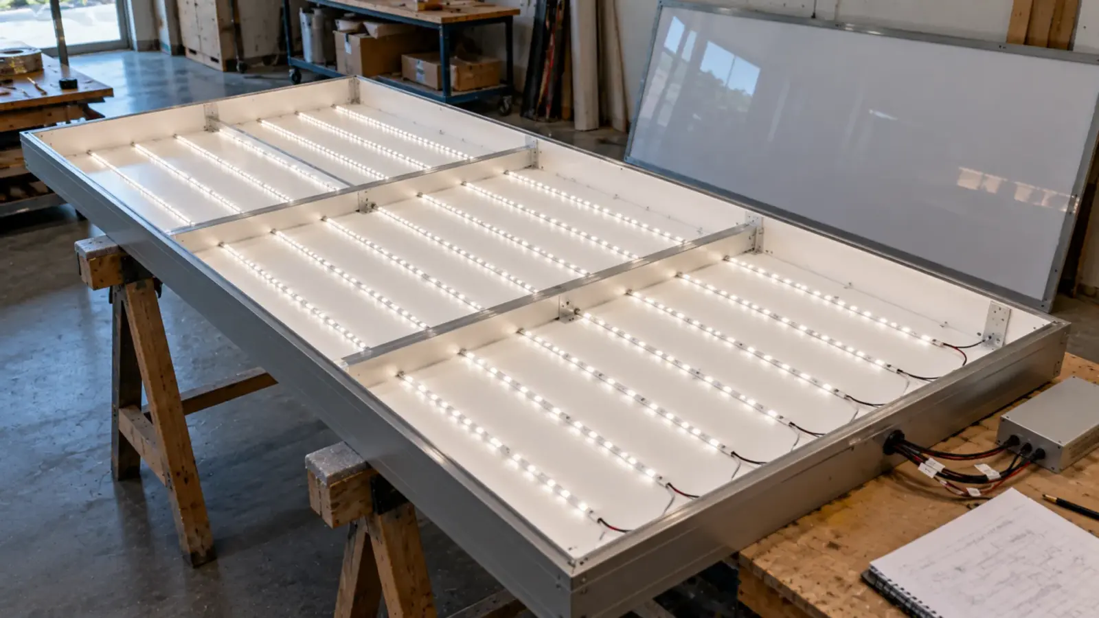
Yes, if the cabinet face is sound and the interior can be cleaned and painted white. Strip rows replace the tubes, an external driver replaces the ballast, and the row spacing comes from the cabinet depth. Plan the rows on a drawing before anything comes apart, then mock up one face section to check the light.
A typical call: the cabinet reads dark in bands every foot, two of the four tubes are out, the ballasts hum, and the owner would rather not buy a new sign. The face is intact, the cabinet is dry inside, and the frame is sound. That is a retrofit job, and the five steps below keep it from becoming a rebuild.
Before You Start
Gather these before you open the cabinet. They decide the layout.
- Cabinet depth, measured from the back panel to the inside of the face.
- Face material and condition: translucent acrylic or polycarbonate, flat or formed. A formed face changes how the light spreads.
- Face size, because rows run across its height or width.
- The power source: where the existing ballast power comes in, and whether a driver can sit outside the cabinet.
- Internal supports: braces and brackets cast shadows with directional LEDs.
A sign-industry source notes that the depth matters most: the distance between the LEDs and the face decides whether the light comes out even. Check the face too. A yellowed or cracked face will not look better lit with LEDs, and it may be the reason to rebuild instead.
Retrofit or Rebuild
A retrofit keeps the cabinet and the face, so check both before you start. Rebuild when any of these is true:
- The face is yellowed, cracked or warped. LED light shows damage that tube light hid, and a new face costs less than a second visit.
- The cabinet leaks or the frame is rusted through. LED strip in a wet cabinet fails, and a sealed strip does not fix a cabinet that fills with water.
- The face is formed and you want a flat one. A flat face changes how the light spreads, and the layout has to be redone from the face out.
- The cabinet is double-faced and too shallow for two sets of rows. Rows for one face can light the other face from behind and wash out its contrast.
If none applies, retrofit. A cabinet in good condition is cheaper to convert than to replace, and the owner keeps the sign’s size, the permit and the mounting.
Step 1: Strip Out the Tubes and Ballasts
Switch off and lock out the circuit, then remove the lamps, the sockets and the ballasts. LED strip is powered by a driver and not by a ballast, so the ballast is not reused. Mark the supply conductors before you disconnect them, because they feed the new driver. Check that the conductors, the connections and the breaker suit the new load, which is usually lower than the ballast load, and replace any insulation that has gone brittle in the cabinet’s heat.
Check the ballast label. According to the EPA, magnetic ballasts made before 1979 may contain PCBs, a magnetic ballast marked “No PCBs” does not, and electronic ballasts are PCB-free. If a magnetic ballast has no marking, the EPA’s guidance is to treat it as containing PCBs or ask the manufacturer. A leaking ballast has to be removed and disposed of under federal rules, and state rules may be stricter. Check the current EPA page and your state agency before you handle an old ballast, and do not put a suspect ballast in the general waste.
Checkpoint: the cabinet is empty, the supply conductors are marked and capped, and the old ballasts are labeled for disposal.
Step 2: Prepare the Interior
Clean the inside of the cabinet and paint it white, or fit white reflective sheet, so the light that bounces back from the face is reused. A dark or rusty interior eats light. Remove or cut back internal supports that sit in front of a planned row, because LED strip is directional and a brace casts a sharp shadow on the face that a fluorescent tube would have hidden.
Note which supports stay. The rows get laid between them, and the row spacing may have to bend around a brace. Seal any hole that lets water in, because LED strip is IP20 unless you choose a sealed type. Leave the drain and vent paths open: a sealed cabinet in summer sun still gets warm, and strip should sit on the painted metal or the white sheet, never on foam or insulation.
Checkpoint: clean white surface, no loose hardware, the supports that remain are on the drawing.
Step 3: Lay Out the Rows
The face does the diffusing, so the question is how far apart the rows can be at your depth. Suppliers publish depth and on-center spacing charts for their own products, and the numbers differ by product, so we do not give one rule. What we can give is the geometry, which you check against a mockup.
The table assumes a 4 × 8 ft (1.2 × 2.4 m) face with rows running the 8 ft length. It shows what each spacing means in strip length and load for two strips from our signage page.
| Row spacing | Rows | Strip length | UT-S2835-120 at 4.4 W/ft | UT-H120-60 at 2.7 W/ft |
|---|---|---|---|---|
| 6 in (150 mm) | 8 | 64 ft | 282 W | 173 W |
| 8 in (200 mm) | 6 | 48 ft | 211 W | 130 W |
| 12 in (300 mm) | 4 | 32 ft | 141 W | 86 W |
This is geometry, not a brightness target. A tighter spacing evens out the face and costs watts, a wider spacing saves watts and risks bands. Pick the spacing from the mockup, then dim the sign to the brightness the site wants.
The cut interval decides how a row fits. The 120V strip cuts every 19.7 in (500 mm), so an 8 ft (96 in) row lands at 78.8 in with 17 in left over at the ends, and the face has a short dark stretch unless two feeds or a shorter row fill it. The SMD strip cuts every 0.98 or 1.97 in (25 or 50 mm), so the same row lands within an inch of the cabinet length. Check the cut interval before you choose the strip, not after.
Wide optics help in shallow cabinets and sparse rows. Our strips have no external lens, so spacing and depth carry the work.
The strip’s own pitch matters too, and you can read it off the spec table. The UT-S2835-120 has 120 LEDs per meter, a pitch of 8.3 mm (0.33 in). The 120V UT-H120-60 has 60 LEDs per meter, a pitch of 16.7 mm (0.66 in), so the face needs more distance to blend its dots. A close-pitch strip hides spots in a shallow cabinet, and a wider pitch wants depth or a diffusing sheet. Pick the strip from the cabinet depth as well as from the power.
Checkpoint: a drawing with row positions, row lengths at the cut interval, feed points and the driver location, signed off by whoever will service the sign.
Step 4: Power and Wiring
Low-voltage strip runs from a driver outside the cabinet, and the 12V or 24V strip has a feed limit: 16 ft (5 m) per feed for the UT-S2835-120. In the table, an 8 ft row is half a feed, so two rows can share one feed. Eight rows then need four feeds, six rows need three, and four rows need two. Plan one jumper between the two rows of each pair, and wire each feed back to the driver with a short run, because a long thin cable drops voltage before the strip sees it.
The 120V strip changes the layout. The UT-H120-60 runs 98 ft (30 m) from one feed, so eight 8 ft rows fit in one feed with jumpers, and no remote driver is needed. It dims by TRIAC or ELV only. Wire it as line-voltage work, and keep the splices in the cabinet sealed and accessible.
Signs are rarely run at full output after dark. Dimming is a driver property: 0-10V or PWM on the low-voltage strips, TRIAC or ELV only on the 120V strip. Put a dimmable driver on the schedule if the sign will be dimmed, and add a photocell or a timer so it follows the hours the owner wants. Some jurisdictions limit sign brightness at night, so ask the permit office what applies.
Keep the power supply outside the cabinet when you can. An external supply is easier to replace than one buried behind the face, and our driver and connector range lists supplies by output. Size each driver with headroom, and label the circuit.
Checkpoint: each row has a feed, each feed has a marked wire, and the driver is reachable without opening the face.
Step 5: Test Before You Close
Power the rows with the face off, then with the face on. Look for the following.
- Dark bands: rows are too far apart for the depth.
- Bright lines on the face: the face is too close to the strip, or the pitch is too wide for the depth.
- Shadows: a support or bracket sits in front of a row.
- Dim ends: the row is too long for its feed, or the cable is too thin.
- Color differences between rows: the rows came from different bins or the strips differ in CCT.
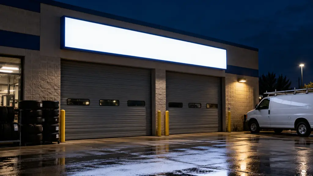
View the face from the street distance and from close up, and photograph it. Leave it running for an hour and look again, because a connector that is loose or a strip that is overloaded shows up as a color shift or a dim end only after it warms. Dim it to the night level, because bands show most when the sign is bright and the surroundings are dark. A mockup of one face section, with two rows and the real face, finds most of these before the whole cabinet is wired.
When It Does Not Look Right
| Symptom | Likely cause | Fix |
|---|---|---|
| Dark bands between rows | Spacing too wide for the depth | Add a row or move rows closer |
| Bright lines on the face | Face too close, or pitch too wide | Add a diffusing sheet or use a closer-pitch strip |
| Shadow from a brace | Support in front of a row | Move the row or the support |
| One row dark | Open jumper or a dead feed | Check the connector and the polarity |
| Bright near the feed, dim at the far end | Row too long for the feed | Feed from both ends or split the row |
| Flicker when dimmed | Driver and dimmer mismatch | Match the dimmer and driver and test on the bench |
Final Checks
- Face and interior clean, supports on the drawing.
- Rows laid at the tested spacing, lengths on the cut interval.
- Every feed within its limit, every wire marked.
- Driver outside the cabinet and reachable.
- Old ballasts handled as the EPA and the state require.
- Photograph taken at night with the sign dimmed.
The strips used in these examples are in our SMD LED strip and 120V LED strip ranges, and we can check the layout against your cabinet drawing if you send it with your quote request.