A trimless LED channel is a drywall coordination job before it is a lighting job. The electrician sets the channel and the wire on blocking before the board goes up, the finisher tapes and floats the flanges with setting compound, and the electrician returns for the strip and the cover after paint. Draw those hand-offs on the detail.
The channel arrives on Monday, the board goes up on Wednesday, and the finisher has never seen a plaster-in profile. Nothing in the electrical drawings says what the finisher needs to know. Most trimless failures are a missed hand-off and not a product fault: a channel fixed to board alone, the wrong compound, a joint in the wrong place, no way back in for service.
Detail Stage: What the Drawing Must Say
The detail drawing has to carry five facts, because the finisher and the framer will not find them in a spec section for lighting.
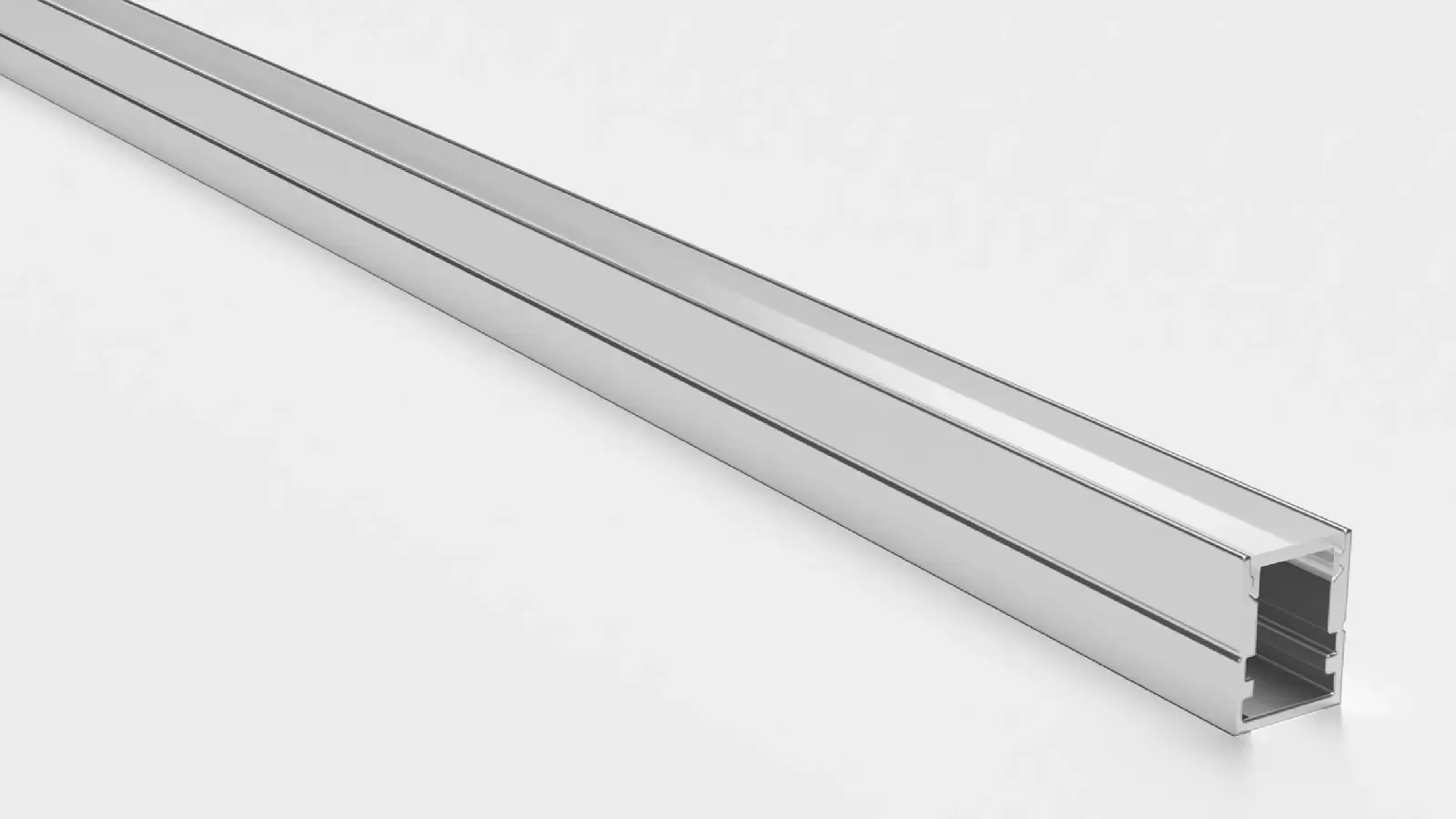
- The channel model and its flange or wing. The UT-CH2020 is a 20.2 × 19.5 mm trimless profile whose mounting wings take joint compound directly. The UT-CH1708 and UT-CH1715 are flanged recessed profiles that plaster into drywall or rout into millwork. Our channel selection guide covers the choice.
- The strip it holds. The UT-CH2020 takes a strip up to 12 mm wide.
- Where it sits, dimensioned from a fixed line, and which board layer it finishes flush with.
- Blocking, drawn, not implied.
- How to get back in: the cover lifts out, and the drawing shows where the driver and the hatch are.
A note on the sheet should also name the finish level of the wall or ceiling, because a lit line reads every flaw near it.
Where the Line Sits
A lit line shows every ripple within a few inches of it, so choose the plane carefully. Put the channel where the ceiling or wall is flattest, and dimension its position from a fixed line, such as the column grid or a wall face, and not from the previous board edge. On long runs, the ceiling is rarely flat to the same tolerance as the channel is straight, and the eye notices when the line and the ceiling drift apart. Where the line must follow a wall that is not straight, say so on the detail, because the finisher and the electrician will then decide which of the two moves.
The choice between a plaster-in line and a surface channel is part of the same decision. If the finish cannot reach the level the lit line needs, a surface channel with a lens is the honest answer, and the channel selection guide shows how to choose.
Blocking and Framing
Fasten the channel to blocking, not to the board alone. One installer guide quotes blocking at 16 in (400 mm) on center, and the principle matters more than the number: the framer provides a solid backing the screws can bite, so the channel stays in plane under the weight of tape and compound. Drywall anchors tend to leave a lip that holds the channel proud of the surface, so avoid them. When the ceiling is already finished and cannot be opened, adding LED strip to a finished hotel room or corridor covers the surface route.
Run the feeder wiring before the board goes up. A feed that has to be fished after the ceiling closes is the most common reason a trimless line is cut open later. Leave a service loop at each run end, and pull a labeled lead to a driver location that has its own access.
Checkpoint: blocking inspected, wire pulled, driver location on the plan, before any board goes up.
Setting the Channel
Cut the channel at the 2 m or 3 m lengths (6.6 or 9.8 ft) on the drawing, with end caps in the kit where a run stops. Hold the line with a laser or a string so the channel sits straight and at the intended depth. Screw it to the blocking, not to the board edge.
Cover the open slot with contractor’s tape before the finisher starts, as the channel makers advise. Compound that gets into the slot or the strip pocket is hard to clean out. Keep the tape on until the last coat.
Checkpoint: the channel is straight, flush with the board face, taped over and photographed before mud.
Corners and Returns
A line that turns is where the detail gets thin. A mitered corner needs two sections cut to meet cleanly, with flange wings that still tape. An inside corner or a return at a column may need a corner piece or two butted sections with tape across the joint. Do not cut the corner on site without the finisher: a joint at a corner is a place where two movements meet, and the tape has to bridge it. Mark each corner on the detail, state whether the line stops or turns, and give the finisher the section lengths so the joints land where tape can reach.
For a feature that runs to a wall, the end cap in the kit closes the channel, and the end of the line is a straight cut with a clean end cap, not a mitered return.
Taping and Mud
Follow the channel manufacturer’s finishing instruction and the finisher’s method. The makers of mud-in channels give a consistent message: use a setting-type compound where there is vibration, and do not use premixed lightweight “soft mud” compound, because it shrinks and cracks along the edge. Embed the flange in compound and tape its edges with paper or fiberglass tape, then feather the compound out into the surrounding board.
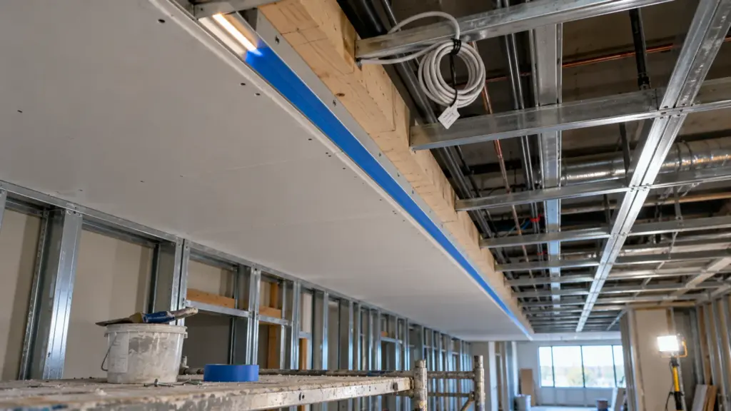
The channel line is a hard edge in a soft surface. A raking or lit line shows every ridge in the compound beside it. Ask the finisher to feather the compound wide and to check it with a raking light at night, before the final coat, and not by day. If the specification calls for Level 5 finish near a lit line, check the finish level in the drywall section before you promise the look. Our guide to wall grazing and washing explains why oblique light shows flaws.
Checkpoint: the flange is taped on both sides, compound is feathered, and the finish is checked with a raking light.
Joints and Movement
Aluminum and board move at different rates. The channel warms when the strip is on, and a 30 °F (17 °C) rise between off and on is a reasonable assumption for planning. The table shows how much each channel length grows on that assumption.
| Channel run | Growth over a 30 °F (17 °C) rise* |
|---|---|
| 6.6 ft (2 m) section | 0.03 in (0.8 mm) |
| 9.8 ft (3 m) section | 0.05 in (1.2 mm) |
| 33 ft (10 m) of joined sections | 0.15 in (3.9 mm) |
*Typical coefficient for common aluminum alloys, about 12.9 µin per in per °F; the temperature rise is an assumption, not a measurement. Use the extrusion maker’s figure and the real temperature.
The numbers are small, and the plaster over them is thinner still. The place that breaks is the joint between two channel sections and the place where a channel crosses a control joint. Plan three things:
- Butt the sections, do not force them. Leave the gap the channel instruction calls for, and put the end caps where a run ends.
- Keep joints away from control joints. InspectApedia notes that continuous drywall beyond roughly 30 ft without control joints can crack from expansion and contraction. If the ceiling has a control joint, end the channel on each side of it and do not bridge it.
- Tape every channel joint, and do not leave a joint at a drywall seam where two movements meet.
Some vendors recommend routing a slot into the board instead of mudding in a flanged channel. That is a different method, so follow the one the channel’s maker specifies and do not mix them on one ceiling.
Service Access
Trimless does not mean unserviceable. The click-in cover lifts out, so a strip can be replaced without opening the ceiling. Write that on the detail, and order spare covers with the job. The driver is the harder part. A remote driver above a hard ceiling needs an access door below it, with the same ID as the register or the O&M sheet.
Keep the strip replaceable: a strip bonded flat to the channel floor comes out with a fresh piece of the same model and CCT, but strip that is trapped under compound does not. If compound reaches the strip pocket, the channel is lost to service.
Checkpoint: one person has stood where the technician will stand and lifted a cover on the first run.
Cover and Paint
Install the covers after the final paint, with the strip lit and tested. Keep touch-up paint and one spare cover on site, because a cover scratched during a service visit is easier to swap than to repaint. Paint the board, not the cover, and mask the cover line on repaint. A cover that is installed before paint collects overspray and shows it as a dirty line. Test the line lit at night, from the viewing positions, before the walls are accepted. Our cover guide covers clear, frosted and opal, and the guide to dots showing through a diffuser covers the deep or shallow line.
A 60 ft Corridor, Counted
A typical run makes the hand-offs concrete. The table counts a single 60 ft (18.3 m) line made from 9.8 ft (3 m) sections.
| Item | Count | Where it matters |
|---|---|---|
| Channel sections | 7 (60 ÷ 9.8 = 6.1, rounded up) | Set before board |
| Joints between sections | 6 | Tape and keep off control joints |
| End caps | 2, one at each run end | In the kit; fit before mud |
| Covers | 7 | After paint |
| Strip | 60 ft plus cut waste | After paint |
| Feeds | At least 4 on a strip limited to 16 ft per feed (60 ÷ 16 = 3.75, rounded up); the model’s run limit and the driver set the real count | Pulled before board |
The count shows why the joint plan matters: six joints is six places for the tape, six places for the finish to crack if it is wrong, and six places a technician will have to find in ten years. If the run crosses a control joint, split it at the joint and count the extra end cap and feed.
Who Does What
| Trade | Task | When |
|---|---|---|
| Architect | Detail, finish level, access, joint plan | Before framing |
| Framer | Blocking at the channel line | Before board |
| Electrician | Set channel, pull feeder, label leads, cover the slot | Before board |
| Drywall finisher | Tape and float flanges with setting compound, feather wide | After board |
| Painter | Paint wall and ceiling; mask cover line | After finishing |
| Electrician | Strip, covers, driver, test lit | After paint |
Mistakes on Trimless Jobs
- Fixing to board alone. The channel sags or shifts under compound.
- Premixed compound. It shrinks and cracks along the edge.
- A joint on a control joint. The ceiling moves and the line cracks.
- Feed after the board. A fished feed leaves a patch scar in the line.
- No test before the last coat. The lit line shows what daylight hid.
What to Put on the Detail
- Channel model, strip width, finish level of the wall.
- Blocking drawn and labeled.
- Compound type and tape on the finisher’s sheet.
- Joint plan against control joints.
- Cover, driver and access hatch locations.
The UT-CH2020 and the flanged recessed profiles are on our channels page, and the cut-and-label option lets us deliver sections pre-cut to your run schedule.