A 98 ft (30 m) aluminum channel grows about 0.47 in (12 mm) when the strip warms it by 30 °F (17 °C). Fix it at every clip and something has to give: the clips, the plaster around it, or the joint where two lengths meet.
Yes, a long channel run needs expansion gaps, because aluminum grows about 0.023 mm per meter for every °C and a channel fixed at every point has nowhere to put the growth. As our planning rule, break a run past about 33 ft (10 m) into sections, fix each section at one point, let the rest slide, and bridge the strip across each gap.
The Formula and a Table
Thermal growth is the length times the temperature change times a coefficient. The Quickparts data sheet for 6063-T5 aluminum, quoting Aluminum Association typical values, gives 23.4 µm/m·°C (13 µin/in·°F), averaged over 68 to 212 °F, and says the figures are not for design. Our channels page names the alloy AL6063 but not the temper, so treat 23.4 µm/m·°C as typical and use the extruder’s figure for a real job. PREFA, a facade profile maker, gives 0.024 mm/m/°C for its own extruded profiles, within about 3% of that. Our trimless channel and wall washer guides used the rounder 23 µm/m·°C (12.9 µin/in·°F), which gives numbers about 2% smaller, such as 3.9 mm for 10 m at 17 °C; the difference is inside the tolerance of the temperature assumptions.
In symbols, growth equals the coefficient times the length times the temperature change. In imperial units, 98.4 ft is 1,181 in, and 1,181 in × 13 µin/in·°F × 30.6 °F (17 °C) is about 0.47 in, which matches the metric 11.9 mm for the same run. Aluminum also expands more than steel or masonry, as our wall washer guide notes, so the channel moves against a surface that moves much less.
At 0.0234 mm per meter per °C, here is the growth of a section against a stable surface, for the two swings we have used elsewhere: 17 °C (30 °F) between strip off and on in an interior, which is the assumption in our trimless channel guide, and 56 °C (100 °F) for a facade between a winter night and a sunlit afternoon, the swing in our wall washer guide.
| Section length | Interior, 17 °C | Facade, 56 °C |
|---|---|---|
| 9.8 ft (3 m) | 1.2 mm (0.05 in) | 3.9 mm (0.15 in) |
| 19.7 ft (6 m) | 2.4 mm (0.09 in) | 7.9 mm (0.31 in) |
| 32.8 ft (10 m) | 4.0 mm (0.16 in) | 13.1 mm (0.52 in) |
| 98.4 ft (30 m) | 11.9 mm (0.47 in) | 39.3 mm (1.55 in) |
The interior numbers are small, and that is the trap. A tenth of an inch will not move a wall, but it can pull a clip, open a butt joint into a visible dark line or crack the compound around a channel fixed at every point. The facade numbers are large enough to see from the street.
What a Fixed Run Does
A channel fixed at every point does not stop growing, it moves the growth somewhere else. Four places to look when a long run misbehaves are the clips, which can pull or loosen; the substrate, where a plastered flange can crack along its length; the joints, where a butt joint opens into a visible dark line or closes into a ridge; and the strip, which can be pulled at a splice. None of these is a code violation, and none shows on the day of installation. They show after the first season or the first full-output week, which is why a mockup left running overnight is a cheap test.
Where the Joints Go
A gap has to absorb the growth of the section on each side of it, so the section length sets the gap. Take a worked case with assumed numbers: a 98 ft (30 m) hospital corridor with one wall-ceiling channel line, and a 17 °C rise with the strip on. Break it into three sections of about 33 ft (10 m). Each section grows about 4.0 mm (0.16 in) in all. Fixed at its middle, it grows half of that, 2.0 mm, toward each end, so each gap takes 2.0 mm from each neighbor, 4.0 mm in total, and the two outer ends of the run need 2.0 mm each. Round the gap up to 5 mm (about 3/16 in) to leave room for installation tolerance. Our channels come in 6.6 ft (2 m) or 9.8 ft (3 m) lengths, so a 33 ft section is four lengths of 3 m, or five of 2 m, butted together.
PREFA’s guidance for its facade profiles recommends a gap of at least 10 mm. That is a rule for cladding in outdoor swings, not for an LED channel, and it is a floor: it is the same order as the 13 mm our table gives for a 33 ft section at the 56 °C facade swing, and below PREFA’s own 14.4 mm for a 6 m profile at a 100 °C difference.
Set the gap for the temperature at installation. A channel hung warm and run warmer only grows, so the gap needs the full growth; a channel hung cold in an unheated shell and then heated needs a wider gap, and one hung hot can also contract below its install length when the building cools. Size the gap from the largest swing the line will see, not from the day it was installed.
Choose where the gap falls. A 5 mm dark break in a continuous line shows at close range, so put it where the eye expects one: at a column, a door head, a change of ceiling height or an inside corner. Our ceiling cloud guide covers keeping a cloud edge clear of pipes and ducts. In a drywall ceiling, end the channel on each side of a ceiling control joint and do not bridge it; our trimless channel guide covers it.
One Fixed Point, Slack Everywhere Else
PREFA’s guidance for extruded facade profiles is a planned arrangement of fixed and sliding points: one round hole near the center of each profile as the fixed point, and slot holes for the rest of the fixings. The same idea applies to a channel section. Pin the section at one point near its middle, and let the rest of it slide so the growth splits to both ends instead of piling up at one.
Our kit ships mounting clips at 19.69 in (500 mm) spacing, and our channels page does not say whether they grip the channel or let it slide. Treat that as a quote question. If the clips grip, a long section needs slotted fixings or clips that float, and one point that does not. If they slide, one fixed point is a screw through the channel at the middle of the section.
Whatever the fixing, set it so each end of the section can move the full amount in the table without a clip binding. Leave the end caps seated and check at the joint after the first warm-up, not at installation. A channel fixed on a cold morning and then heated by a full run of strip is where a joint opens.
The Strip Across the Gap
A gap in the channel is a gap in the line, and the strip has to cross it. Do not run one continuous strip through a joint that is meant to move, because the strip will be pulled or buckled as the channel grows. Cut the strip at the gap, and bridge it. Our drivers page lists a strip-wire-strip connector, BXB, which bridges two strips across a gap with a wired jumper between them, and its maximum current is 5 A. That connector is listed for 8, 10 and 12 mm strip, so a wider strip in a wider channel takes a different jumper, which is a quote item. Leave a short slack loop in the jumper so the movement does not load the joint, and keep the jumper inside the channel behind the cover.
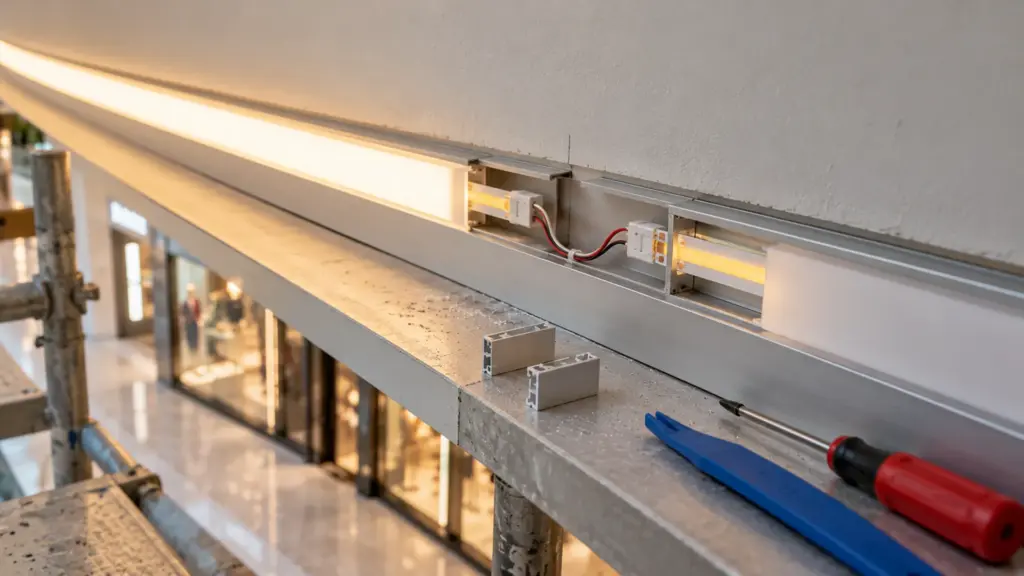
Check the current at the feed. A BXB jumper on the feed side of a run carries the whole run’s current, as our connector guide explains, so keep it inside the 5 A rating. For a gap deep in a run, the jumper carries only what is downstream. Our guide to cutting and connecting strip covers cut points.
Interior, Trimless and Facade Runs
The amount of movement also depends on what heats the channel. In a corridor the main source is the strip itself, and a channel carrying a high-output strip in a closed cove can run warmer than the room around it. On a facade the sun and the night dominate, and a dark finish on the channel absorbs more sun and loses more heat at night. Use the swing the line will really see, which is the strip’s heat plus the room’s, or the weather’s, not a single number for every job.
The three cases differ in how much movement the surface can take. A surface channel on a wall can float on its clips. A trimless channel plastered into drywall is held by the compound, so a section fixed rigidly in the wall has the least room, and the movement shows as a crack along the flange. Keep trimless sections short and end them at control joints. A facade channel faces the full swing and the sun, and our wall washer guide has its own movement table for aluminum fixtures; follow the extruder’s coefficient and the maker’s joint detail.
The heat comes from two sources, the room and the strip. Our thermal performance guide covers how to rank and test strip power against a profile, and a high-power strip in a closed profile raises the swing above the 17 °C used here. Our channel selection guide covers the profile.
If the Run Is Already Built
A continuous run that is already fixed and misbehaving can be relieved. Choose a planned break, such as a column or a door head, cut a relief gap in the channel there, cap both cut ends, and bridge the strip with a jumper and a slack loop. Release the fixings on each side of the new gap so the sections can slide, and keep one fixed point in each. Our guide to cutting and connecting strip covers the cut and the connection.
Checks Before the Channel Is Fixed
- The section length, the temperature swing and the movement from the table, for the actual alloy and the extruder’s coefficient.
- Joints placed where the eye expects a break, with each gap at least the section’s movement, rounded up.
- One fixed point per section and slack at every other fixing, confirmed with the clip’s maker.
- The strip cut at each gap, bridged by a jumper with a slack loop, inside the 5 A rating.
- A re-check of each joint after the first full-output warm-up.
The channel sizes above are in our LED channels and diffusers range, and the jumper is in our drivers and connectors range.