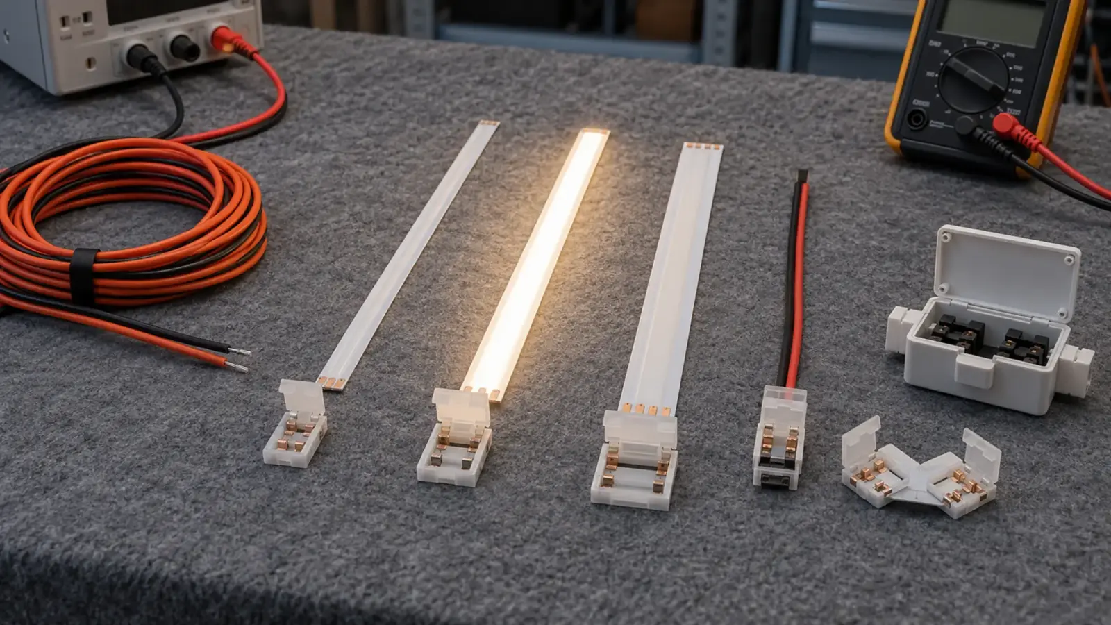
A connector has to match five things: the number of conductors, the PCB width, the current, the IP rating and the way the joint is made. Miss one and the joint is the part that fails, often weeks after install and often inside a channel, where it is hard to reach.
You have 12 mm RGBW strip, a 16 ft run and a joint that will sit in a ceiling slot. Work through five steps in order, and check each one against the strip’s datasheet. The figures below come from our drivers, controllers and connectors page and from the strip spec tables.
Step 1: Count the Conductors
The conductor count follows the circuit, not the strip’s length. Every pad on the strip needs a matching contact and a wire.
| Strip circuit | Conductors | Example |
|---|---|---|
| Single color | 2 | UT-C480-8 |
| Tunable white, 2-wire | 2 | UT-T576-8 |
| Tunable white, 3-wire | 3 | UT-T640-10 |
| RGB | 4 | UT-R60-10 |
| RGBW | 5 | UT-RW60-12 |
| RGB+CCT | 6 | UT-RCCT72-12 |
| SPI addressable | 3, or 4 on breakpoint resume | UT-A720-12-BP |
| DMX512 addressable | 5 | UT-A540-12-DMX |
Our connector table lists single color, CCT, RGB and RGBW circuits. For RGB+CCT, SPI and DMX strip, ask for the connector at quote, because those pin counts are not on that table. A connector with too few pins does not fail loudly; it leaves a color channel dark or lights the wrong one.
Step 2: Match the PCB Width
The strip’s PCB has to sit flat in the connector, so width is a hard limit.
- Strip-to-strip, wire-to-strip and strip-wire-strip connectors: 8, 10 and 12 mm PCB.
- PCB corner connector: 8 and 10 mm, single color and CCT.
- Mounting clips: 8 to 20 mm, mechanical only.
Two groups fall outside those widths. Ultra-narrow COB, such as UT-C400-3 at 2.7 to 3 mm, and wide strip, such as UT-C960-15 at 15 mm and UT-C1600-30 at 30 mm, are not on the connector table. They are joined with solder, or with the strip’s own connection if the series has one; the solder-free series, such as UT-C320-6-SF and UT-T480-7, use the method on their datasheet.
Check the width on the strip’s own spec line, not on the model number, and check it again if you swap a strip for another model later.
Step 3: Check the Current
Our strip-to-strip, wire-to-strip and strip-wire-strip connectors, and the corner connector, are rated 5 A. The strip’s current is its watts per foot times the length, divided by the voltage. A joint at the feed point carries the whole run, so check that case.

| Strip and run | Load | At 24V | At 12V |
|---|---|---|---|
| UT-C320-8, 16 ft (5 m) | 38 W | 1.6 A | 3.2 A |
| UT-C480-8, 16 ft (5 m) | 51 W | 2.1 A | 4.3 A |
| UT-S2835-240, 16 ft (5 m) | 107 W | 4.5 A | not offered at 12V |
| UT-C960-15, 10 ft (3 m) | 76 W | 3.2 A | not offered at 12V |
| UT-C1600-30, 10 ft (3 m) | 122 W | 5.1 A | not offered at 12V |
The figures are our arithmetic from the spec tables: watts per foot times the single-feed run limit, divided by the voltage. Two points follow.
First, 12V doubles the current for the same watts. A full 16 ft run of UT-C480-8 at 12V is 4.3 A, close to the connector’s 5 A. Second, the highest-output strips outrun the connector: UT-C1600-30 at its 10 ft limit is 5.1 A, over the 5 A rating, and it is wider than any connector on the table. For loads like that, the joint is soldered, or the run is split so that each feed carries less.
Keep a margin. Treat a joint that is warm to the touch as a joint to redo, because heat at a connector is how a small resistance becomes a failure. Our guide to whether LED strip lights are a fire hazard explains why.
Step 4: Pick the Seal for the Location
The connector table lists IP20 and IP62 for strip-to-strip connectors, and IP20, IP62 and IP65 for wire-to-strip and strip-wire-strip connectors. So a connector on our table reaches IP65.
For an Dust-tight, and protected against temporary immersion in water. The usual rating for wet or outdoor runs that are not submerged all the time. or IP68 strip, the joint has to be built to that level and not to the connector’s. Vendor guides for waterproof connectors point the same way. Signlite’s selection guide suggests IP65 or IP67 strip-to-wire connectors for most outdoor jobs and gel-filled connectors or a sealed junction box for harsher conditions, and an IP rating on a clip covers the joint, not the strip end or the wire entry beyond it. We confirm the joint design for IP67 and IP68 runs at quote.
Two rules cover most jobs. Use a connector at least as sealed as the strip, and seal every cut end and every wire entry with the matching silicone end cap and adhesive. The system is only as protected as its weakest part, and an IP rating is not a wet location rating; see our wet location guide.
Step 5: Choose the Joint Type
The joint type follows what the joint has to do.
| Joint | Our connector | What it does | Use it for |
|---|---|---|---|
| Strip-to-strip | BB | Butts two cut ends together with no soldering | Continuing a run past a cut |
| Wire-to-strip | XB | Lands a driver lead or an injection feed on the strip | Every feed point; a pigtail is this joint with leads |
| Strip-wire-strip | BXB | Bridges two strips across a gap or around a corner with a wired jumper | Gaps and turns |
| PCB corner | Corner connector | Turns the strip at a corner | 8 and 10 mm strip, single color and CCT |
| Soldered joint | Not a connector | A wire soldered to the pads | High current, wide or narrow strip, permanent joints |
| Junction or terminal box | Not on our table | Lands wires in a box away from the strip | Serviceable runs, signage, harsh locations, per vendor guides |
A box is the right answer more often than it is used. If a joint has to be serviced and the strip is behind a finished surface, bring the wires to a box and make the strip joint short. How to make the joint itself, clip or solder, is covered in our guide to cutting and connecting LED strip.
- 1Conductors2 to 6Pins match the circuit
- 2PCB width8, 10, 12 mmStrip seats flat in the clip
- 3Current5 A ratingThe feed joint carries the run
- 4SealIP20 to IP65At least as sealed as the strip
- 5Joint typeBB, XB, BXBClip, solder or box
A Worked Example: Three Joints on One Job
A 24 ft (7.3 m) cove in a lobby, with the driver in a closet at one end, shows how the five steps change the answer from one joint to the next.
| Joint | Where | What it carries | What the steps say |
|---|---|---|---|
| Feed | Driver lead to the first strip | The whole first run, 2.1 A on UT-C480-8 at 16 ft | Wire-to-strip connector (XB), 8 mm PCB, under 5 A, dry interior, IP20 is enough |
| Run break | Two 12 ft pieces meeting mid-cove | Current for the second piece only | Strip-to-strip connector (BB), same width, lower current than the feed |
| Corner | Where the cove turns | The second piece’s current | PCB corner connector at 8 mm, or a strip-wire-strip jumper (BXB) if the corner is tighter than a corner connector allows |
Two things stand out. The feed joint carries the most current, so it is the one to solder if the margin is thin, and the one to place where it can be reached. And all three joints are dry-interior joints, so IP20 connectors are enough; moving the same cove outdoors would change step 4 for every one of them.
Wire at the Connector
A connector joins the strip to a wire, and the wire has its own limits. LED Supply says its IP67 clip works with 20 to 22 AWG stranded wire, and that 22 AWG is its best size. That is one maker’s rule for one connector. For ours, the accepted wire gauge is not on the connector table, so ask at quote.
Two habits protect any connector. Support the wire so its weight does not hang on the joint: a pulled wire is the commonest cause of a lifted pad. And size the wire for the current and the run, using the voltage drop tables in our voltage drop guide, because a thin wire at a good connector still starves the strip.
How Connectors Fail
| Failure | Cause | What it looks like |
|---|---|---|
| Strip will not seat | Connector for the wrong PCB width | Loose strip, no contact |
| One color or channel dark | Too few pins for the circuit | Wrong or missing color |
| Flicker | Latch not closed, or strip shifted | Intermittent at the joint |
| Joint warm | Current close to the 5 A rating | Heat, then a dead section |
| Pad lifted | Strain on the wire pulled the copper off the board | Dead section after a tug |
| Water at the joint | Wire entry or cut end unsealed | Corrosion, dead run after rain |
Most of these appear after the ceiling is closed. A bench test of the joint at full load, and a tug test, catch the first four before that happens.
Joint Checklist
- The pin count matches the circuit, and the connector table lists it.
- The PCB width is on the connector’s width list, or the joint is soldered.
- The current at the joint is under 5 A with margin, at the voltage you are using.
- The joint is at least as sealed as the strip, and every cut end and wire entry is sealed.
- The joint type suits the job, and a box is used where the joint has to be serviced.
Send the strip models, the run lengths and the locations and we will return the connectors for each joint, with a soldered or boxed joint called out where the table does not cover it: request a quote.