A bigger driver does not fix a dim far end. The voltage is lost after the driver: in the feed cable, in the strip’s thin copper, and at every joint. LED strip voltage drop is current times resistance, so the fixes that work cut the current or the distance: a higher voltage, more feed points, or heavier feed wire.
NEC references below are general. The authority having jurisdiction (AHJ) and the NEC edition your area has adopted decide what applies on your job.
The Math: Why Doubling Voltage Quarters the Drop
Voltage drop in a strip is the current multiplied by the resistance of the copper it flows through. Current depends on power and voltage: I = P ÷ V. Take one run of 156 W, the load of 65 ft (20 m) at 2.4 W/ft, and the same wattage draws very different current at each voltage:
| Supply voltage | Current at 156 W | Relative drop, as a share of the supply |
|---|---|---|
| 12V | 13 A | 16 times |
| 24V | 6.5 A | 4 times |
| 48V | 3.25 A | 1 time |
Halving the current halves the volts lost along the same copper. Because the supply voltage also doubles, the loss as a share of the supply falls to a quarter. That is the 16 : 4 : 1 ratio.
Two assumptions sit behind it: the same wattage, and the same copper, length and construction. Real products differ, so read the table as the reason higher voltage helps, not as a forecast for a specific reel. The 12V and 24V rows are a comparison at the same load, not products we list at 65 ft.
Where the Volts Go
The drop shows up as a brightness gradient: brightest at the feed, dimmest at the far end. On a cove, the first few feet look right and the last stretch looks tired.
On white strip the far end dims. On color strip it can also shift. Our RGB vs RGBW guide explains why a long RGB run turns pink: red LEDs need less voltage than green and blue, so red holds on as the voltage falls.
Three parts of the circuit take a share of the voltage:
- The feed cable. Both conductors carry the current, so the loop is twice the one-way distance. A thin cable on a long pull can lose more than the strip itself.
- The strip copper. The PCB traces are thin, and the current falls along the run as each LED takes its share. This is the drop the run limit on a spec table describes.
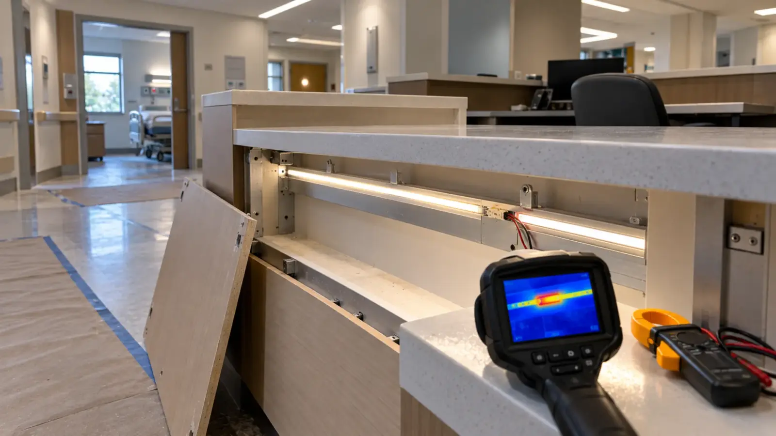
- The joints. Every connector, solder pad and terminal adds a small resistance. One loose clip connector can cost more than 10 ft of strip, and it runs warm while it does.
A bigger driver changes none of these. It supplies the same 24V at its terminals, and the losses happen after that.

Measure It Under Load
A voltmeter on an unlit strip reads full voltage everywhere, because no current flows. Measure with the run lit at full output, and read three points:
- At the driver output terminals.
- At the strip’s feed point, across the positive and negative pads.
- At the far end of the run, across the last pads.
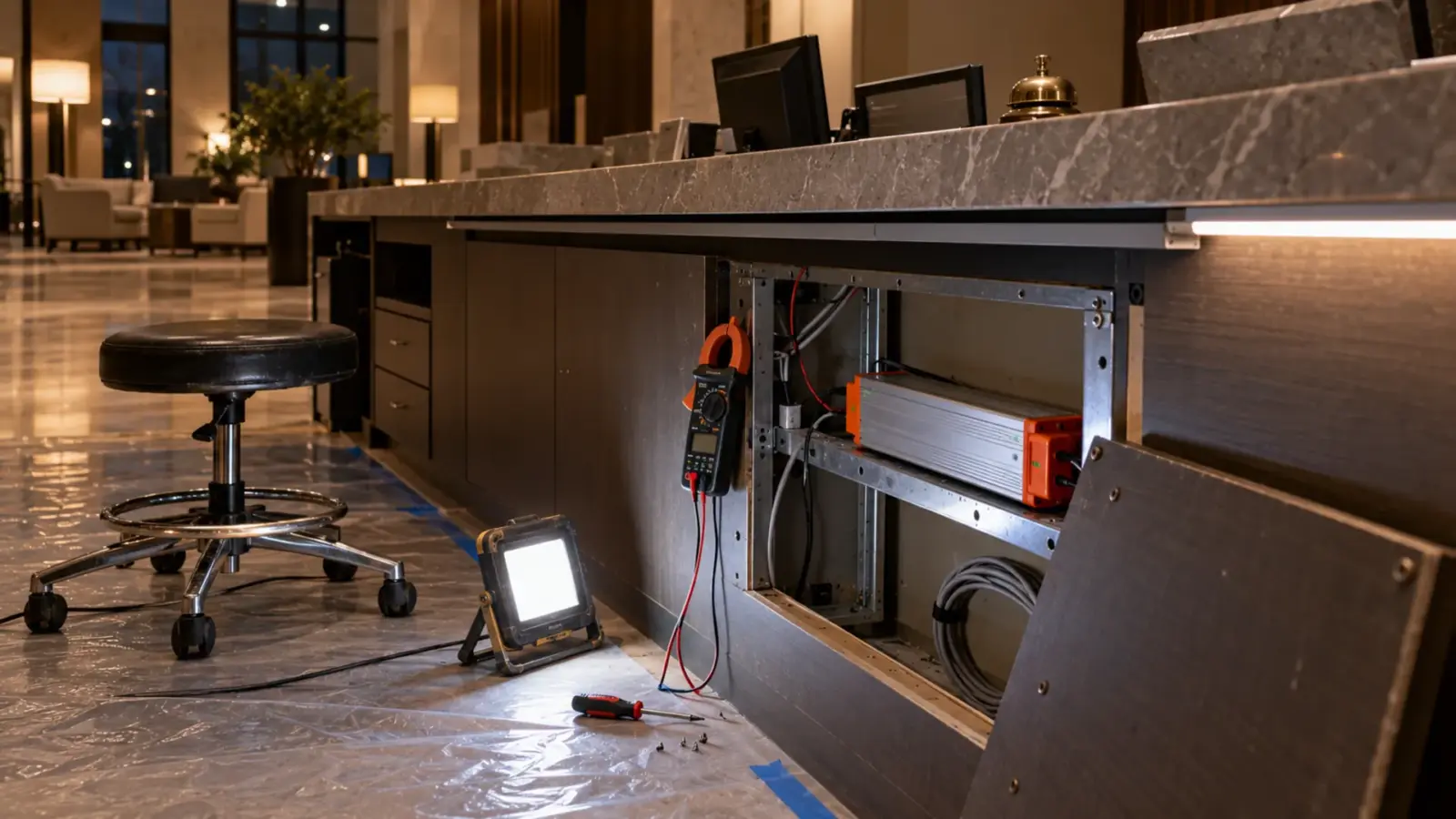
Point 1 minus point 2 is the feed cable and its joints. Point 2 minus point 3 is the strip copper. If point 1 already reads low, look at the driver, its load, and its input before anything else. A connector that reads a noticeable drop across itself, or feels warm, is a joint to remake.
Write the three readings on the as-built for each run. Our installation guide folds this into the bench test, before the strip goes into the channel.
Run Limits From Our Spec Tables
Our spec tables give a run limit for each model, not for each voltage class. A model listed at 12V/24V carries one limit, so the numbers below belong to the models, not to a voltage.
| Model | Voltage | Power | Run limit | Load at full run |
|---|---|---|---|---|
| UT-C320-8 (COB) | 12V/24V | 2.4 W/ft | 16 ft (5 m)/feed | About 38 W |
| UT-S2835-120 (SMD) | 12V/24V | 4.4 W/ft | 16 ft (5 m)/feed | About 70 W |
| UT-C384-8 (COB) | 24V | 3.0 W/ft | 32 ft (10 m), no voltage drop | About 96 W |
| UT-C312-8 (COB) | 12V/24V | 3.4 W/ft | 32 ft (10 m), no voltage drop | About 108 W |
| UT-S2835-160-48V (SMD) | 48V | 4.4 W/ft | 49 ft (15 m) single feed | About 215 W |
| UT-C480-8-48V (COB) | 48V | 2.4 W/ft | 65 ft (20 m) single feed | About 156 W |
| UT-C480-8-CC (COB) | 24V constant current | 2.3 W/ft | 65 ft (20 m) constant current | About 149 W |
| UT-S2835-140-CC (SMD) | 24V constant current | 3.7 W/ft | 65 ft (20 m) constant current | About 240 W |
The last column is our arithmetic, power per foot times the run limit, rounded down. It is not a spec sheet value, and it matters in the Class 2 section below. The 65 ft models are on the COB LED strip and SMD LED strip pages; all of them are IP20. Anything beyond a model’s limit needs another feed.
Three Fixes: Feed Points, 48V, or Constant Current
| Fix | How it works | What it needs | What to watch |
|---|---|---|---|
| Power injection | Adds feed points along the run | More feed cable, a driver sized for the total load | Polarity at every feed |
| 48V constant voltage | Same wattage at half the current of 24V | A 48V supply | Class 2 limits and location |
| 24V constant current | The strip regulates current along the run | A matched constant-current driver | Dimming path |
Power injection
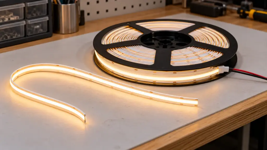
Injection means feeding the run at more than one point. Where the table says 16 ft (5 m)/feed, plan one feed per 16 ft, so a 48 ft cove takes three. Feeding both ends puts the dimmest point in the middle; feeding the middle puts it at both ends. Run each feed back to the driver on its own cable, keep every feed on the same supply, and check polarity at each one. A reversed feed on a live strip can destroy it.
48V constant voltage
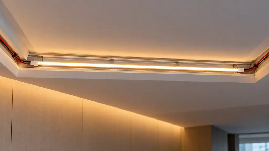
48V is the simplest wiring for a long run: one feed and one cable pair. UT-C480-8-48V runs 65 ft (20 m) from a single feed. Our drivers, controllers and connectors page lists 24V and 12/24V supplies, so a 48V supply is matched at quote.
24V constant current
Constant-current strip regulates the current in each segment, so the far end stays as bright as the near end. Our COB page lists UT-C480-8-CC at 65 ft (20 m) from one end. It needs a constant-current driver matched to the strip, and the dimming path works differently from constant-voltage strip, so confirm it before you order. Our dimming guide covers the control side.
Our opinion: on a dry indoor run that needs one feed over 32 ft (10 m), both are reasonable. Pick constant current when the rest of the job is 24V; pick 48V when the 48V supply is easy to place.
Feed Wire: The Drop Before the Strip
The feed cable is the part of the drop you choose with a wire size. The voltage lost in it is:
ΔV = I × R × (2 × one-way length) ÷ 1,000, with R in ohms per 1,000 ft.
The table runs that formula for a 96 W run at 24V, which draws 4 A: one full 32 ft (10 m) run of UT-C384-8. It assumes nominal copper resistance at 68°F (20°C) and counts the cable only, not the strip or the joints. For any other load, gauge or home-run length, our feed-wire voltage drop calculator runs the same formula and names the thinnest gauge that stays inside your limit.
| Feed wire | Ohms per 1,000 ft | 25 ft one-way | 50 ft one-way |
|---|---|---|---|
| 26 AWG | 40.8 | 8.2 V (34%) | 16.3 V (68%) |
| 22 AWG | 16.1 | 3.2 V (13%) | 6.4 V (27%) |
| 18 AWG | 6.39 | 1.3 V (5.3%) | 2.6 V (10.7%) |
| 16 AWG | 4.02 | 0.8 V (3.4%) | 1.6 V (6.7%) |
| 14 AWG | 2.53 | 0.5 V (2.1%) | 1.0 V (4.2%) |
| 12 AWG | 1.59 | 0.3 V (1.3%) | 0.6 V (2.6%) |
Three readings of the table. A 26 AWG lead, the size often pre-soldered on strip, cannot carry a full run back to a closet: it loses a third of the voltage in 25 ft. On a 25 ft pull at 4 A, 16 AWG keeps the cable loss under about 3.5%, and 14 AWG under about 2%. And distance doubles the loss, so a driver placed near the run often beats a heavier cable.
Warm cable reads higher. NEC Chapter 9, Table 8 lists DC resistance at 167°F (75°C), and those values run roughly a fifth to a quarter above the room-temperature figures used here. At 48V the same 96 W draws 2 A, so every cell in the table halves in volts and falls to a quarter as a percentage. For Class 2 output, the cable must also be CL2 or CL3 rated; our Class 2 driver guide covers that.
48V and the Class 2 Limit
48V changes the code picture. A Class 2 DC source is limited to about 100 VA; verify the exact figure in the Chapter 9 table of your NEC edition. And where wet contact is likely, the 2023 text as quoted in our wet location guide sets a lower voltage limit of 30 V DC.
Two consequences follow. A 48V run in a wet location cannot sit inside that limit, and our 65 ft models are IP20 anyway, so a wet run uses IP-rated 24V strip with a feed at least every 16 ft (5 m). And a full 65 ft run of UT-C480-8-48V loads about 156 W, more than one Class 2 circuit can carry. Wire that output as non-Class 2, or split the run so that each section has its own Class 2 output.
Not every long run reaches the ceiling. UT-C384-8 at 32 ft loads about 96 W. Our Class 2 drivers are rated at 60 W each, though, so even that run needs a supply from outside the Class 2 group or two outputs.
Worked Example: A 96 ft Corridor Cove
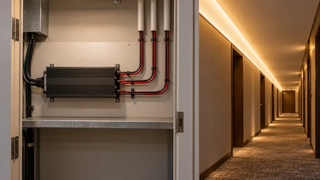
Take 96 ft of corridor cove, the driver closet at one end, and UT-C384-8 as the strip. The spec table lists 32 ft (10 m) per run, so the cove becomes three runs of about 96 W each, 288 W in all.
Keep the connected load at or below 80% of the driver rating. That means 120 W of rating for one run and 360 W for all three. A 150 W driver such as UT-D150-24-L fits one run, and a 400 W driver such as UT-D400-24-L carries all three. Neither is in our Class 2 group, so plan the output wiring as non-Class 2 unless the nameplate says otherwise.
Now the feeds. Each run gets its own cable from the closet. The third run starts 64 ft away, so its cable loop is 128 ft at 4 A. From the formula, 14 AWG loses about 1.3 V (5.4%) on that pull and 12 AWG about 0.8 V (3.4%). If neither is acceptable, move the driver toward the middle of the corridor or add a second driver at the far end.
The same corridor on 48V still needs one feed per 65 ft of strip, plus the right supply and class rules. The saving is real only when runs are long and few.
Decision Table
| Situation | Use | Why |
|---|---|---|
| Short run within the model’s per-feed limit | 24V constant voltage | Simplest wiring |
| 32 ft (10 m) run on a model listed for it | UT-C384-8 or UT-C312-8 | Listed at 32 ft with no voltage drop |
| Long dry run, one feed up to 65 ft (20 m) | 48V or 24V constant current | One feed, no injection |
| Long run in a wet location | IP-rated 24V strip with feed points | Our 65 ft models are IP20; 48V is above the wet-contact limit |
| Driver far from the run | Heavier feed cable or a closer driver | Cable loss doubles with distance |
Common Mistakes
- Fixing drop with a bigger driver. The supply voltage at the terminals does not change, and the loss happens after them.
- Feeding a full run on the strip’s own leads. The thin pre-soldered lead is for the last foot, not for the pull back to the closet.
- One cable for several feeds. Each feed point gets its own cable, or that cable becomes the bottleneck and the hottest conductor in the ceiling.
- Reversed polarity at an injection point. Check every feed with the meter before you power the run.
- Measuring with the strip off. An unloaded reading shows full voltage everywhere and hides the problem.
- Choosing 48V and finding the code rules later. The supply, the Class 2 limit, and the location all need checking before the order goes in.

FAQ
How far can you run 12V, 24V, or 48V LED strip?
It depends on the model, not only the voltage. On our spec tables most standard strip is listed at 16 ft (5 m) per feed, some models at 32 ft (10 m), the 48V SMD at 49 ft (15 m), and the 48V and constant-current COB at 65 ft (20 m) from a single feed.
Why does the end of my LED strip look dimmer or pinker?
Voltage falls along the strip, so the far end gets less than the first LEDs. White strip dims. RGB strip shifts toward pink because green and blue need more voltage than red. Add a feed point, shorten the run, or check the feed cable.
Do I need 48V LED strip for long runs?
Not always. 48V constant voltage is one option; 24V constant current and power injection are the others. Choose 48V when one feed matters most, the run is dry, and the Class 2 limits are acceptable.
Can I power LED strip from both ends?
Yes. Feeding both ends cuts the drop and moves the dimmest point to the middle. Use the same supply for both feeds and keep polarity correct at each end.
How much voltage drop is acceptable?
There is no single code figure for strip. Many designers aim for a few percent in the feed cable and rely on the model’s run limit for the strip. The useful test is visual and measured: the far end looks like the near end, and the loaded reading at the far end is close to the feed.
Rules of Thumb
- Fix the circuit, not the driver: shorter runs, more feeds, heavier or shorter feed cable.
- Measure under load at three points, and write the readings on the as-built.
- Never feed a full run on the thin leads that come on the strip.
- Use 48V or constant current for long dry runs, and settle the driver class before the wiring plan.
The run limits and loads above come from our COB and SMD spec tables; we check them against your layout at quote.