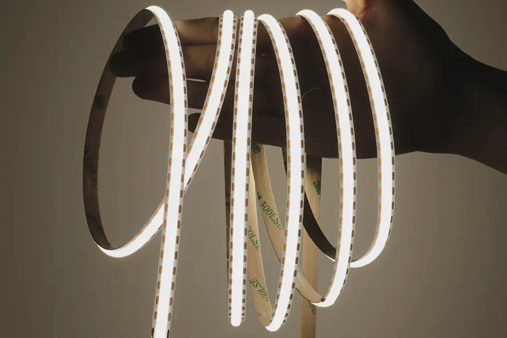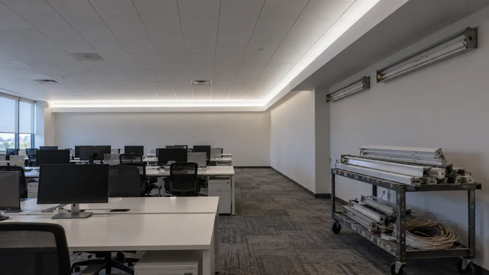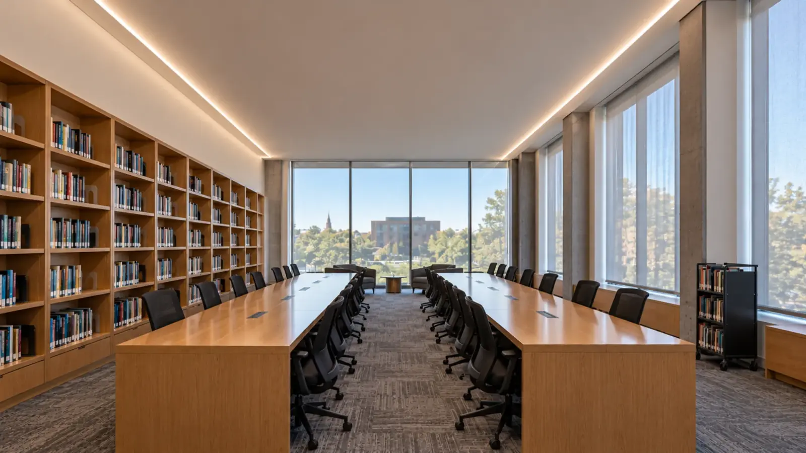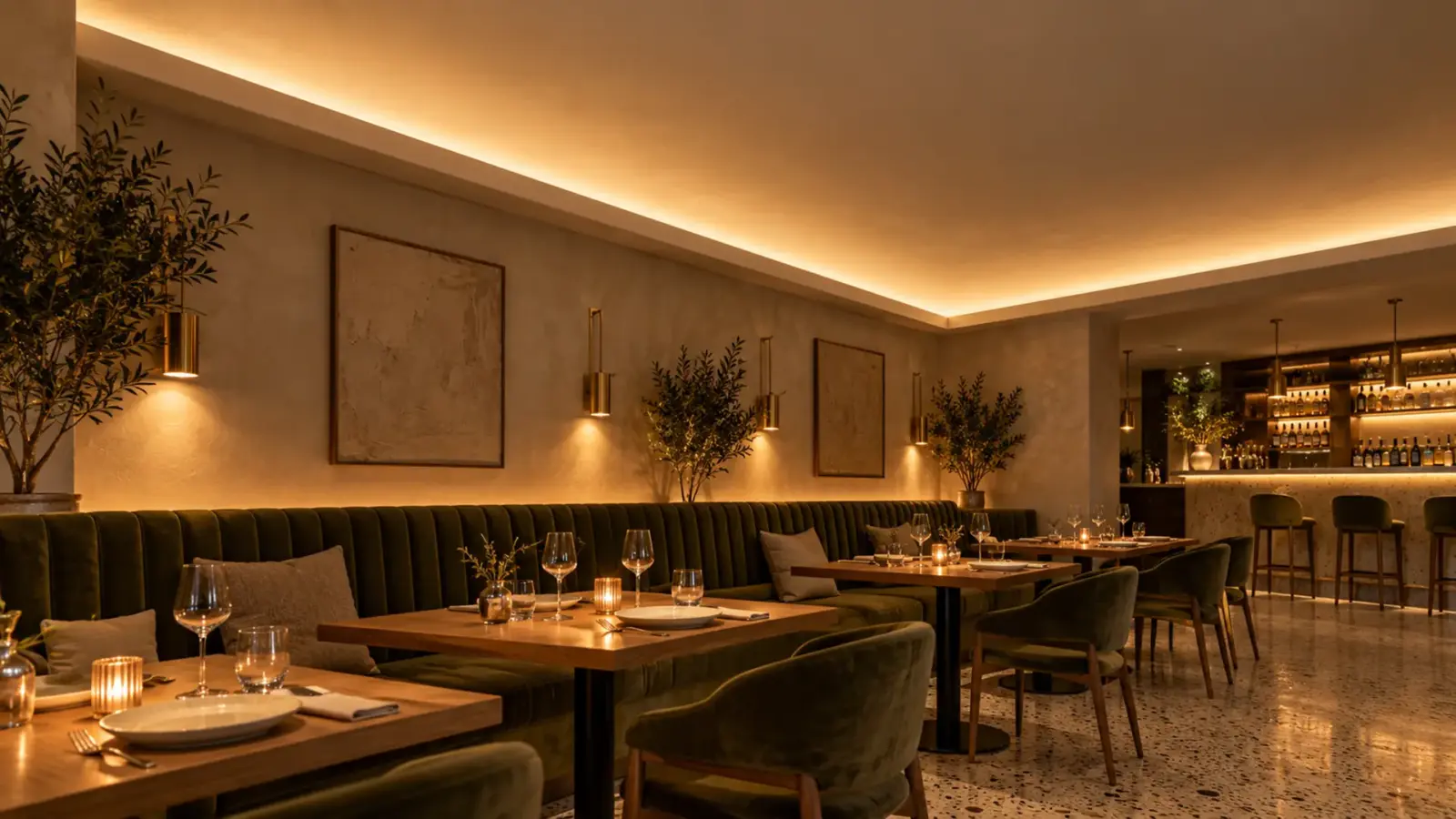
A 20 ft cove of UT-CSP-320-N puts out roughly 5,900 lumens at the strip. Over the 60 sq ft of ceiling it washes, that is an upper bound near 99 footcandles; a real cove delivers a fraction. Lumens per foot is measured at the strip, not on the ceiling, so work backward from the light you need there.
LED Strip Lumens per Foot: What the Number Measures
The usual fix for a dim cove is a brighter strip. It rarely works, because lumens per foot (lm/ft) is the light leaving the strip, measured bare on a bench. The room only gets the share that lands on the surface.
Three more units sit next to it. W/ft is the power the strip draws. Lumens per watt (lm/W) is lm/ft divided by W/ft. UT-CSP-320-N lists 296–316 lm/ft at 3.05 W/ft, which is the 97–103 lm/W on its spec table. Per-meter figures convert at 3.28 ft per meter, so UT-SFS80-8 at 528–600 lm/m is the same strip as 160–183 lm/ft.
On the surface side, a footcandle (fc) is one lumen per square foot, and a lux is one lumen per square meter. One footcandle is about 10.76 lux. The right fix works backward from the fc target on the surface to the lm/ft the strip must supply. The cove section itself, setback, lip and sightlines, is on our cove lighting application page.
Target Surface: Start with Footcandles, Not Strip Specs
The target comes from the project, not from the strip. On commercial work, take it from the lighting design, the specification, or the owner’s brief, and write it as footcandles or lux on a named surface: a counter, a wall, a floor, a ceiling. We do not quote a target level here, because the right level depends on the space and on what the spec says.
Name the surface and its area before you open a datasheet. The same strip gives very different numbers on a counter inches away and on a ceiling feet away. A cove lights the ceiling first and the room second, so the room gets what bounces off it.
Conversion: From Target to Lumens per Foot
Start with one line.
Light needed from the strip = target fc × surface area ÷ delivered fraction
The delivered fraction is the share of the strip’s lumens that reaches the surface after spill, distance, reflectance, and any diffuser. A photometric layout or a mock-up gives it. We do not publish a general number, because it changes with every cove and every finish.
Here is the opening example run forward. The surface is 20 ft × 3 ft (60 sq ft), lit by 20 ft of UT-CSP-320-N at its low-end 296 lm/ft, which is 5,920 lm.
| Delivered fraction | Light on the surface |
|---|---|
| 100% (upper bound) | about 99 fc |
| 50% | about 49 fc |
| 25% | about 25 fc |
Now run it backward. Suppose the spec calls for 30 fc, a figure used here only as an example. That needs 1,800 lm on the surface. At a delivered fraction of 50%, the strip must put out 3,600 lm, or 180 lm/ft over 20 ft.
Check that against the tiers further down. UT-SFS80-8 (160–183 lm/ft) falls short at its low end. UT-SFS160-8 (307–365 lm/ft) clears it with margin. Always use the low end of the range, because a datasheet gives a range and the reel can land anywhere in it.
Direct light changes the fraction, not the method. Take a 12 ft counter run on a 24 sq ft surface, again with the same example target of 30 fc. That needs 720 lm on the surface. If a mock-up reads a delivered fraction of 70%, the strip must supply about 1,030 lm, or roughly 86 lm/ft over 12 ft. Even the lowest tier in the table below, UT-CSP-300-MC12 at 123–128 lm/ft, is above that. On direct jobs, brightness is usually a dimming and glare question, not a shortage.
A Cove, Worked Through
A cove is the hardest case for this method because the light reaches the room only after it bounces off the ceiling. Three things in the cove section move the delivered fraction more than the strip does.
- Setback. The gap between the strip and the ceiling sets how far the wash spreads. A strip tight to the ceiling puts a bright band near the lip and leaves the middle of the ceiling darker; a deeper cove spreads the same lumens over more area at a lower level.
- The lip. A tall lip hides the strip from more viewing positions, and it also catches light. The part of the beam that lands on the back of the lip never reaches the ceiling.
- The ceiling finish. A matte white ceiling sends much more of the wash back into the room than a mid-tone or dark ceiling. The same strip in the same cove can look generous on white paint and dim on a colored ceiling.
Take a typical corridor cove: 20 ft long, a 3 ft wide band of ceiling to light, a target of 30 fc on that band used here only as an example. That is 1,800 lm on the ceiling. If a mock-up in the real cove reads a delivered fraction of 40%, the strip must supply 4,500 lm, or 225 lm/ft. UT-CSP-160-MC (249–293 lm/ft) clears it at its low end, and UT-SFS160-8 (307–365 lm/ft) clears it with room to dim. If the ceiling is later painted a darker color, the fraction drops and the same strip falls short, so record the finish in the spec along with the strip.
Mock-Up: Measure the Delivered Fraction
The delivered fraction is the one number you cannot read off a datasheet, and a short mock-up gives it. Mount 5 ft of the candidate strip in the real channel, behind the real diffuser, in its planned position. Read the light on the target surface at several points with a light meter, and average the readings.
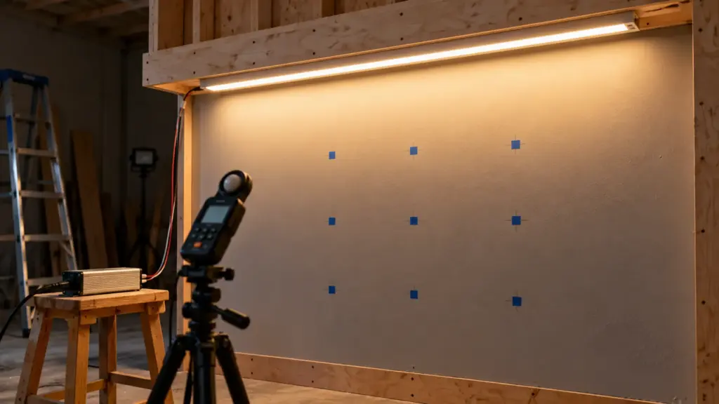
Then divide. Delivered fraction = average fc × the surface area the sample lights ÷ the sample’s lumens. As an example reading, 5 ft of UT-CSP-320-N at its low end is 1,480 lm. If it lights 15 sq ft and the meter averages 30 fc, that is 450 lm on the surface, a delivered fraction of 30%. Scale it to the full run: 20 ft × 296 lm/ft × 30% is about 1,780 lm on 60 sq ft, close to 30 fc. If the mock-up used the real diffuser, its loss is already inside that 30%.
Losses: What Never Reaches the Surface
Every loss between the strip and the surface lowers the delivered fraction. Some of them show up in our own spec tables, so they are numbers, not guesses.
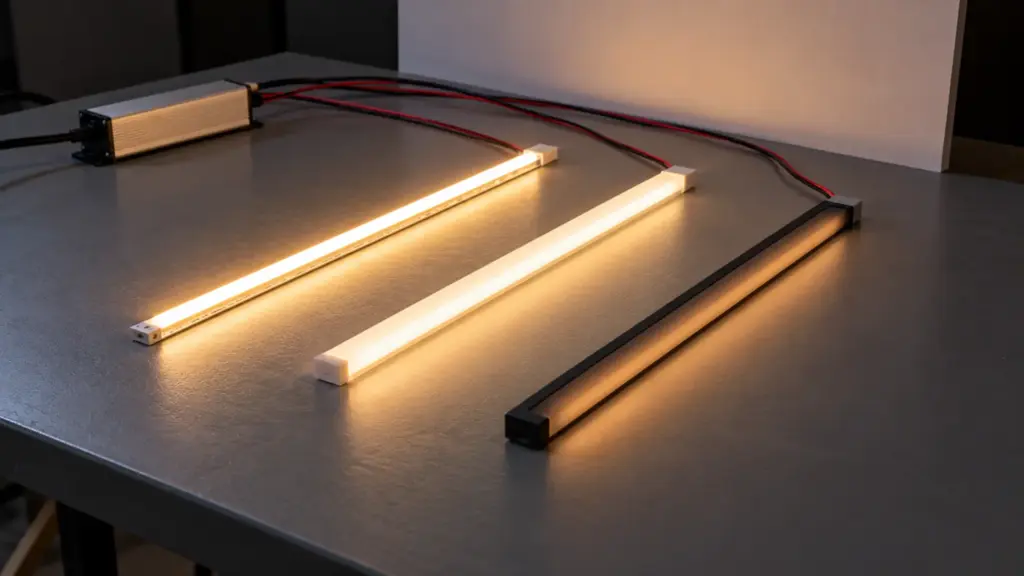
Diffusion. UT-CSP-320-N (bare, 296–316 lm/ft) and UT-CSP-320-DD (dome diffused, 238–271 lm/ft) both draw 3.05 W/ft. The diffused build gives about 14–20% less light for the same power. Our channel page puts opal PC diffusers at roughly 70 to 80% transmission and clear ones at roughly 90 to 95%, and our under-cabinet guide shows how that loss changes the strip choice.
Sleeves and jackets. The IP68 build UT-CSP-320-68 (293–302 lm/ft) gives up almost nothing against the bare strip. The white-jacket UT-CSP-320-68WJ (183–201 lm/ft) is about 36–38% lower, and the black-jacket UT-CSP-320-68BJ (91–104 lm/ft) is about two thirds lower, or roughly half the output of the white jacket. Pick the sealed build for the environment, then size the run from its lm/ft, not the bare figure.
Dimming headroom. Our rule: size the strip so the target is met at about 80% output. That leaves the dimmer room to trim at commissioning, and the strip is not at full power on day one. Datasheet lumens are also initial output, and output declines over the life of the strip, so the headroom pays twice.
One caution on double counting. If the delivered fraction came from a mock-up with the real diffuser, the diffuser loss is already inside it. If it came from a bare strip, take the diffuser loss off again before you pick a tier.
Voltage drop. The far end of a long run gets less than the feed end, and brighter strip draws more watts per foot, so it drops faster. Read the voltage drop guide before you lock a run length.
Output Tiers: Match the Strip to the Job
Pick by the lm/ft you calculated, then by the other constraints on the row. Values are low to high in the range each model lists.
| Model | lm/ft | W/ft | Notes |
|---|---|---|---|
| UT-CSP-300-MC12 | 123–128 | 1.83 | 12V, 0.39 in cut, 2700–4000K |
| UT-SFS80-8 | 160–183 | 1.5 | Ra≥95, 24V |
| UT-CSP-160-MC | 249–293 | 2.93 | Mini cut, 24V |
| UT-CSP-320-N | 296–316 | 3.05 | CRI >90, 24V |
| UT-SFS160-8 | 307–365 | 2.9 | Ra≥95, 24V |
| UT-CSP-480-N | 396–415 | 4.39 | CRI >90, 24V |
| UT-SFS80-10 | 439–483 | 4.4 | Ra≥95, 24V, 10 mm |
| UT-SFS160-8-HO | 585–702 | 5.9 | Ra≥95, 24V, high output |
Two readings from the table. On the mini-cut series, density is a cut-interval decision, not a brightness decision: the three 24V builds all draw 2.93 W/ft and give comparable output. And the full-spectrum series gives more light per watt than the standard CSP at similar loads, in 2700K, 3000K, and 4000K at Ra≥95. The high-CRI guide covers when that tier earns its place.
Three picks from the example numbers show how the table reads. The counter run above needs far less than the bottom row delivers, so the choice is about cut length and dimming, not output. The 180 lm/ft cove, if its 50% fraction came from a bare-strip mock-up and will sit behind a diffuser costing about 20%, needs 180 ÷ 0.8 = 225 lm/ft at the strip. UT-CSP-160-MC (249–293 lm/ft) clears that at its low end, and UT-SFS160-8 clears it with more room. A tall ceiling or a long throw pushes the fraction down and the requirement up, which is where the high-output rows earn their W/ft.
The CSP LED strip and SMD LED strip pages list the full ranges. COB lm/ft is not in the table because the full photometric files ship with the quote.
Driver Load: Watts per Foot Comes Next
Brightness turns into load. Load in watts is W/ft times feet, and our sizing rule keeps it at or below 80% of the driver’s rating.
Run the 20 ft example. UT-CSP-320-N at 3.05 W/ft over 20 ft is 61 W, so the driver must be rated at least 76 W. That is above our Class 2 range, which stops at 60 W. There are two ways out: one non-Class 2 driver, or two 10 ft runs at 30.5 W each on two UT-D40-24-C2 drivers (32 W usable each).
A brighter strip changes the answer. UT-CSP-480-N at 4.39 W/ft draws 43.9 W per 10 ft, which fits one UT-D60-24-C2 (48 W usable). The eleventh foot pushes it past 48 W, so each 10 ft of that strip needs its own driver.
One caution. 60 W is the rating of our Class 2 drivers, not the Class 2 limit, as the Class 2 guide explains. Driver models are on the drivers, controllers and connectors page.
Job Targets: Cove, Under-Cabinet, Accent, Wall
According to HitLights, retail guidance for strip brightness runs in these ranges.
| Use | lm/ft |
|---|---|
| Accent and mood | 100–350 |
| Under-cabinet | 175–525 |
| Task, close to the surface | 280–437 |
| Task, farther from the surface | 500–1,000 |
| Indirect (hotel and lobby among them) | 375–562 |
| Industrial and tube replacement | 500–950 |
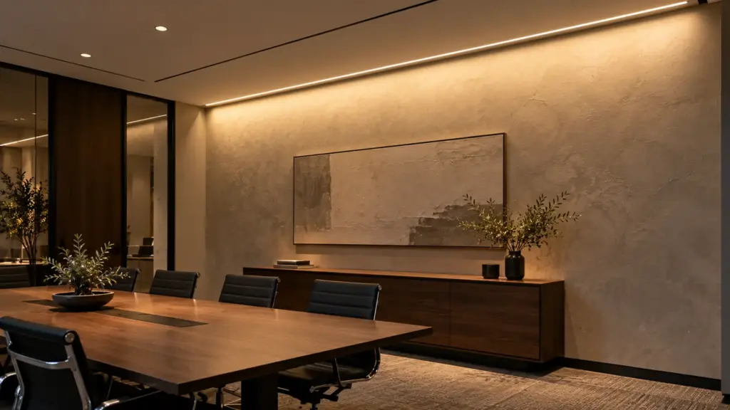
The close and far task ranges differ because distance spreads the same lumens over a larger area, so a farther surface needs more light from the strip. Treat these as starting points for a mock-up, not spec values. A cove is indirect, so start from the indirect range and let the mock-up settle it.
Wall washers break the comparison. UT-WB27 lens bars all draw 8.2 W/ft, yet UT-WB27-1060 gives 494 lm/ft, UT-WB27-45 gives 551, and UT-WB27-2030 gives 675. The lens decides where the light goes, so lm/ft alone does not rank them. For those jobs, work from setback and beam angle, as in the wall washer beam angle guide.
Datasheet Traps: Reading the Number Honestly
- Ranges. 296–316 is a range. Calculate from the low end.
- Per meter. Divide lm/m by 3.28 before comparing it to lm/ft.
- Bare versus installed. A bare strip figure does not include the channel or diffuser.
- CCT. The same strip shifts with color temperature: UT-CSP-512-CCT lists 238 lm/ft at 2700K and 244 lm/ft at 6500K.
- Color strips. Lumens are weighted to the eye. UT-CSP-280-DD lists 67 lm/ft red, 256 green, and 49 blue at the same 3.05 W/ft, so lumens say little about how a color strip looks.
FAQ
How many lumens per foot do I need for cove lighting?
Work backward from the target footcandles on the ceiling and the delivered fraction. As a starting range, HitLights lists 375 to 562 lm/ft for indirect lighting. Confirm with a mock-up before you order the run.
Is higher lm/ft always better?
No. Higher lm/ft means more watts per foot, more driver load, and faster voltage drop. UT-SFS160-8-HO gives 585–702 lm/ft at 5.9 W/ft, while UT-SFS80-8 gives 160–183 lm/ft at 1.5 W/ft. Pick the lowest output that meets the target at 80% output.
How do I convert lumens per foot to lux?
Multiply lm/ft by the run length and divide by the surface area in square meters. That is the 100% upper bound. The opening example is 5,920 lm over 60 sq ft (5.57 sq m), about 1,060 lux or 99 fc, before any loss.
Can I use a brighter strip and dim it?
Yes, and it is often the safer spec, because a dimmer can trim an oversized strip but nothing can add light to an undersized one. Size the driver for full output, though. Dimming lowers the load while the strip is dimmed, not the rating the driver must carry. Confirm the control path at quote.
Does a diffuser reduce lumens per foot?
Yes. UT-CSP-320-DD gives about 14–20% less light than UT-CSP-320-N at the same 3.05 W/ft.
What is the difference between lm/ft and W/ft?
W/ft is power in and lm/ft is light out. Their ratio is Lumens per watt: how much light the strip gives for the power it draws. Higher means less heat and less driver load per foot.. UT-CSP-320-N draws 3.05 W/ft and lists 296–316 lm/ft, which is 97–103 lm/W.
Order Checklist: Eight Checks
- A target in fc or lux, on a named surface.
- The surface area and the run length.
- A delivered fraction from a layout or a mock-up.
- A mock-up in the real channel and diffuser, if the job is a cove or a visible line.
- The low end of lm/ft for the actual build: bare, diffused, or sleeved.
- Output sized to meet the target near 80%.
- Load at or below 80% of the driver rating, with the Class 2 range checked.
- Far-end voltage drop checked for the run.
Lumens per foot is one part of a cove. Setback, lip height, sightlines and finishes are on our LED strip cove lighting page, with the configurations we usually supply.
Have a target level, a run length and the ceiling finish? Send all three and we will size the strip and driver for the cove: request a quote.