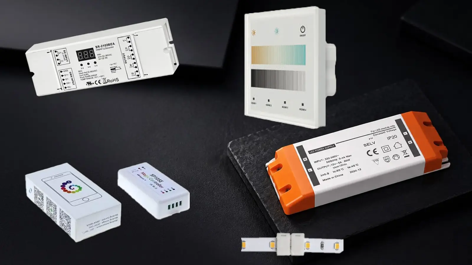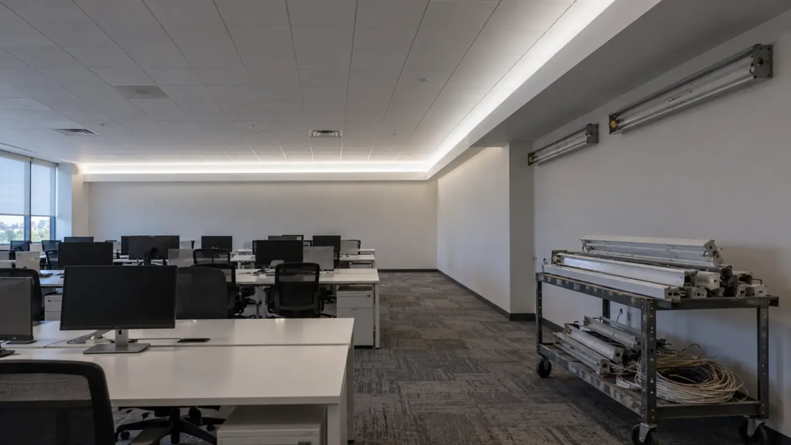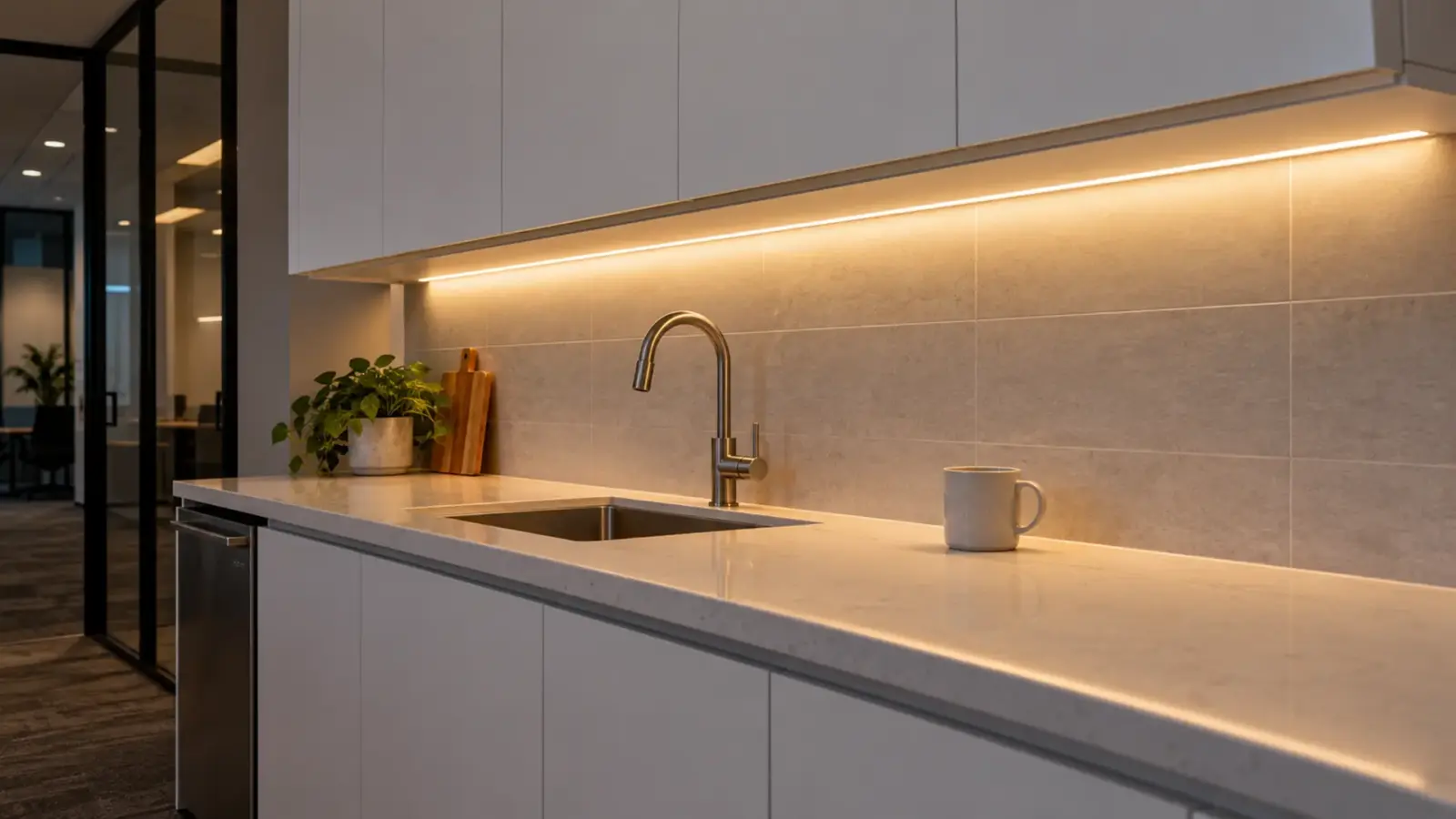
Under-cabinet LED strip comes down to four calls, and the driver decides two of them: how much strip one driver carries, and where that driver lives for the next ten years. The calls below apply to commercial and multifamily millwork: kitchenettes, office pantries, nurse stations, lobby bars.
- Strip: 8 mm COB at Ra≥90 for exposed runs. SMD works inside an opal channel, and full-spectrum Ra≥98 SMD earns its place over stone, food, or merchandise.
- Channel: a slim surface channel with an opal diffuser. Size the strip up one density step for the light the opal absorbs.
- Driver size: keep the load at or below 80% of the rating. That is 15 ft (4.5 m) of UT-C480-8 on a 60 W Class 2 driver, or 10 ft (3 m) on a 40 W one.
- Driver location: dry, ventilated, and reachable later. Not the toe kick, and not a sealed soffit.
Our under-cabinet and millwork application page covers the whole detail, including toe-kicks and casework. NEC references here are general; the authority having jurisdiction (AHJ) and the NEC edition your area has adopted decide what applies on your job.
Strip Type: Choosing the Under-Cabinet LED Strip
Most guides stop at “choose COB.” On a job the real question is what the strip has to survive: an eye at standing height, a polished backsplash, a client who cares how stone or food looks.
Start with whether the strip is seen directly or in a reflection. An exposed strip on a light rail, or one that shows in a stone counter, has to read as one line. COB LED strip does that without a diffuser, because the phosphor is continuous across the chips. For under-cabinet work, these four 8 mm models cover most jobs (all Ra≥90, 24V figures):
| Model | Power | Cut increment | Max run per feed | Pick it for |
|---|---|---|---|---|
| UT-C320-8 | 2.4 W/ft (8 W/m) | 0.98 or 1.97 in (25 or 50 mm) | 16 ft (5 m) | Lowest load, so the most strip per driver |
| UT-C384-8 | 3.0 W/ft (10 W/m) | 1.23 in (31.25 mm) | 32 ft (10 m) | The middle step, 24V only |
| UT-C480-8 | 3.2 W/ft (10.5 W/m) | 0.98 or 1.97 in (25 or 50 mm) | 16 ft (5 m) | More output behind an opal diffuser |
| UT-C528-8-FC | 4.0 W/ft (13 W/m) | Any point (free cut) | 16 ft (5 m) | Cabinets that never land on a cut mark |
Cut increment matters more here than on a long cove. A 1.97 in increment can leave a gap of almost 2 in at the end of a cabinet, and a visible face frame shows it. Free-cut strip closes that gap.
SMD strip belongs inside a channel with a diffuser. It is the right call when the job needs color quality beyond Ra≥90: UT-S2835-480-FS carries Ra≥98 at 5.5 W/ft (18 W/m), 480 LEDs per meter, with a 0.98 in (25 mm) cut. Look at it over stone, produce, bakery cases, or retail goods. The reason to choose it is color, not dots.
Keep one color temperature across every run that shares a backsplash, and across any adjoining cove or downlights.
The short rule: exposed strip gets COB, strip inside a channel can be either, Ra≥98 means the full-spectrum SMD, and a cabinet that fights the cut marks gets free-cut. Decide the strip first, because its watts per foot set the driver size in the load math below.
Channel and Diffuser: Hide the Strip, Not the Light
Under-cabinet strip lives in a surface-mount aluminum channel for two reasons. The channel hides the strip from a standing viewer, and the aluminum is a heat sink: our COB page notes that mounting in an aluminum channel lowers the operating temperature and protects lumen maintenance. Surface mount is the right family here because the cabinet is already built. A recessed profile needs open millwork to route into.
Match the strip’s PCB width to the channel’s maximum strip width, then pick by height under the cabinet:
| Channel | Size (W×H) | Max strip | Use it for |
|---|---|---|---|
| UT-CH1013 | 13×10 mm (0.51×0.39 in) | 10 mm | The slim default under upper cabinets |
| UT-CH1207 | 12×7 mm (0.47×0.28 in) | 8 mm | Shallow rails and reveals, 8 mm strip only |
| UT-CH2415 | 24×15 mm (0.94×0.59 in) | 15 mm | The deep dot-free profile for SMD that has to look continuous |
Every model in the range is offered with a clear or opal PC diffuser. Clear transmits roughly 90 to 95% of the strip’s output but leaves individual LEDs visible. Opal transmits roughly 70 to 80% and blends them into one line. Where the fixture is seen directly, spec opal and size the strip up one step. In practice that means UT-C480-8 where UT-C384-8 would have been enough behind a clear cover.
That step costs 0.2 W/ft, and it shows up again in the load math below. Browse the full LED channel and diffuser range for end caps and clips by model.
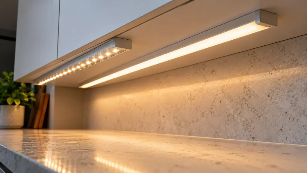
Strip Placement: Front, Middle, or Back
Position decides what the strip lights: the counter, the backsplash, or both. Toward the front edge, aimed down and slightly back, lights the work surface and keeps the strip out of a standing viewer’s sight line behind the light rail. Toward the wall lights the backsplash and leaves the counter dimmer.
Polished stone changes the math. A strip near the front edge can show as a bright reflected line on the counter. An opal diffuser softens it, and moving the channel back a little loses it. Push it too far and the work surface goes dark. The fix is cheap: tape a short length in place before you stick or cut anything, and look at it from standing height with the counter finish in place. A few minutes there beats re-mounting a finished run.
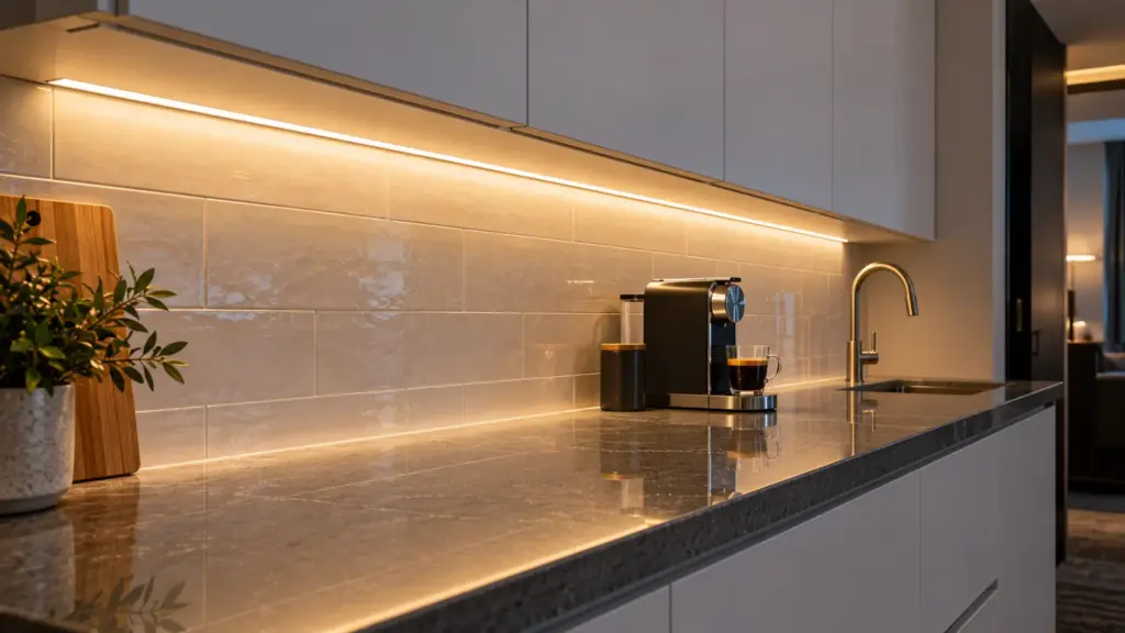
Driver Size: How Much Strip One Driver Carries
Load is watts per foot times feet. Keep it at or below 80% of the driver’s rating, which is the sizing rule in our SMD page FAQ. Our Class 2 power supplies add a second limit: they are rated 24V output at 60 W or less per circuit. The 80% rule on a 60 W supply stops you at 48 W, so on a Class 2 job one driver tops out near 15 ft of UT-C480-8. Past that, you add a driver.
Lengths below are the smaller of the 80% load limit and the strip’s run limit per feed, rounded down to whole feet:
| Strip (24V) | Load | On UT-D40-24-C2 (32 W usable) | On UT-D60-24-C2 (48 W usable) |
|---|---|---|---|
| UT-C320-8 | 2.4 W/ft | 13 ft (3.9 m) | 16 ft (4.8 m), run limit |
| UT-C384-8 | 3.0 W/ft | 10 ft (3 m) | 16 ft (4.8 m) |
| UT-C480-8 | 3.2 W/ft | 10 ft (3 m) | 15 ft (4.5 m) |
| UT-C528-8-FC | 4.0 W/ft | 8 ft (2.4 m) | 12 ft (3.6 m) |
| UT-S2835-120 | 4.4 W/ft | 7 ft (2.1 m) | 10 ft (3 m) |
| UT-S2835-480-FS | 5.5 W/ft | 5 ft (1.5 m) | 8 ft (2.4 m) |
| UT-S2835-240 | 6.7 W/ft | 4 ft (1.2 m) | 7 ft (2.1 m) |
A typical job shows where this bites. An office pantry has three cabinet runs of 7, 6, and 5 ft, all UT-C480-8. That is 18 ft at 3.2 W/ft, or 57.6 W. At 80%, the job wants a 72 W supply, and our Class 2 range stops at 60 W. One UT-D60-24-C2 would run at 96%.
The fix is two drivers, split by cabinet bank. The 7 ft and 6 ft runs share one UT-D60-24-C2: 13 ft, 41.6 W, 69% of its rating. The 5 ft run takes a UT-D40-24-C2: 16 W, 40% of its rating. A single larger supply such as the 96 W UT-D96-24-010 carries the load in one box, but it sits outside our Class 2 group, so the wiring conversation changes. The trade for staying on Class 2 at a safe load is a second driver.
Split by location, not by arithmetic. Each driver should feed the cabinets it is closest to, so every lead stays short.
Driver Location: Six Places, Ranked
The driver is the part you will touch again, so rank locations by how you service them years later, not by how clean the install looks on day one:
| Rank | Location | Service access | Heat and water | Notes |
|---|---|---|---|---|
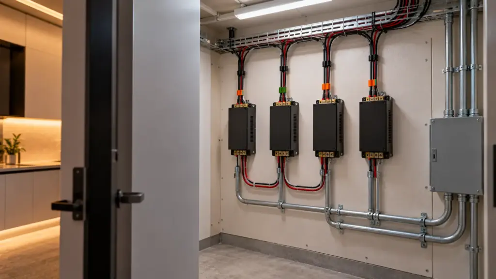
| 1 | Remote: equipment closet, or ceiling space with a hatch | Best | Ventilated, dry | Best for two or more zones; the lead gets long (see below) |
| 2 | Inside an adjacent cabinet, in a blank-cover box | Good | Needs air; keep stored goods off it | The usual choice for one zone |
| 3 | On top of the upper cabinets | Ladder, and behind trim | Heat collects near the ceiling | Fine if the top stays reachable without removing finishes |
| 4 | Sink base, high on the side wall | Easy | Leak and splash risk | Only above the leak line, never on the floor |
| 5 | Plug-in driver at a receptacle above the cabinet | Easy | Cord and plug rules vary | Retrofits and small jobs |
| 6 | Toe kick | Poor, panel removal | Trapped heat, floor water | Not a driver location |
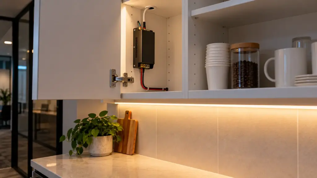
Three rules hold in every location. Leave air around the driver; never seal it into a cavity. Keep it reachable without demolition. Label which driver feeds which run, once at the driver and once at the strip lead.
On a nurse station or a long pantry wall, one remote location for all the drivers beats a driver in every bay. The next service call goes to one door, the labels sit side by side, and the cabinets stay free of boxes. The trade is longer leads, and the Lead Wire section puts that in volts, not guesses.
Our UT-D40-24-C2 and UT-D60-24-C2 are IP20 cases, which means dry locations. For a damp spot, our IP67 potted drivers exist in the same range; check the output class and dimming before you swap one in. The full lineup is on the drivers, controllers, and connectors page.
Junction Boxes, Splices and Service
Every under-cabinet run has two connections someone will open again: where line voltage reaches the driver, and where the driver’s output meets the strip leads. Plan both before the cabinets are hung.
The line-voltage side. A hardwired driver needs its line-voltage connection in a box or in the driver’s own wiring compartment, made the way its listing allows. Electricians on the Mike Holt forum describe a common commercial pattern: one larger junction box in an adjacent closet or utility space that houses several drivers, with the switch legs and home runs brought to it. That keeps every line-voltage splice in one serviceable place instead of inside three finished cabinets.
The low-voltage side. The same threads mention 18/2 CL2 stranded or 20/2 solid cable from the driver to the strip, and they warn about two traps. Insulation-displacement connectors on tape often accept only small wire, so check the connector’s gauge range before you pull heavier cable. And 14/2 building wire is hard to land on the small connection boxes used for tape. Splices on the low-voltage side should still be accessible, and where they sit inside a cabinet, put them in a box or a cover rather than loose behind the light rail.
Service. Assume the driver will be replaced once. Mount it with screws, not adhesive; leave enough slack in the leads to pull it out; and label the driver, the box, and the strip lead with the same run number. On a nurse station or a long pantry wall, a one-page sheet in the closeout package that maps drivers to runs saves the first service call an hour.
Drill feed holes through the cabinet bottoms or the adjacent taller cabinet before the countertop goes in, and agree the route with the millwork installer. Cable that has to be fished after the backsplash is set is cable that gets pinched.
Lead Wire: The Drop Before the Strip
A remote driver trades a hidden box for a longer lead. Voltage drop on that lead is separate from the drop along the strip, and the two add. According to NEC Chapter 9, Table 8, 14 AWG stranded uncoated copper is 3.14 Ω per 1,000 ft. The lead carries current out and back, so count both conductors.
Here is the math for 15 ft of UT-C480-8, which is 48 W:
| Case | Current | Round-trip length | Drop on 14 AWG | Share of supply |
|---|---|---|---|---|
| 24V, driver 10 ft away | 2.0 A | 20 ft | 0.13 V | 0.5% |
| 12V, driver 10 ft away | 4.0 A | 20 ft | 0.25 V | 2.1% |
| 24V, remote driver 40 ft away | 2.0 A | 80 ft | 0.50 V | 2.1% |
| 12V, remote driver 40 ft away | 4.0 A | 80 ft | 1.0 V | 8.4% |
At 24V, a short lead is nothing. A 40 ft remote run on 14 AWG is about 2%, which is workable. At 12V, the same 48 W doubles the current, and the lead’s share of the supply grows fourfold. That is why 24V is the default. The strip’s own drop is covered in our guide to LED strip voltage drop.
A common rule of thumb is to keep lead drop under about 3%. The pigtail leads that come on a strip are often thinner than 14 AWG, and resistance climbs quickly as wire gets thinner, so check the gauge before you stretch one.
Dimming: Match the Driver to the Wall Control
Dimming is decided at the driver. Reusing an existing TRIAC wall dimmer means a TRIAC driver: UT-D60-24-TRC is 60 W, 120 V input, forward and reverse phase. New commercial work with a 0-10V wall panel means UT-D60-24-C2-010: Class 2, 60 W, 120 to 277 V input. On new commercial jobs, spec 0-10V. Use TRIAC only when the dimmer is already on the wall. The UT-CTP-010 is the one-zone 0-10V touch panel in the same range, with a 100 to 277 VAC input.
TRIAC dimmers have a minimum load, and one short cabinet run can fall under it. Check the pairing before you order; dimmer compatibility lists ship with every quote. The trade-offs between protocols are in our guide to 0-10V, TRIAC, and DALI.
Code Notes: What to Confirm with the AHJ
These are questions to ask, not rulings. Practice varies by jurisdiction, and the answers are the AHJ’s to give.
- Class 2 on this circuit. Our Class 2 range is 24V output at 60 W or less per circuit. Ask how the AHJ counts a circuit when you split a job across drivers. The difference is covered in Class 2 vs non-Class 2 drivers.
- Driver access. Article 100 of the NEC defines “readily accessible” as reachable without tools (other than keys), climbing over or under, removing obstacles, or portable ladders. Whether a given driver location must meet that, and whether an access panel or hatch counts, is a question for the AHJ. Ask before the cabinets close.
- Where the driver may sit. Inside a cabinet or in a soffit or ceiling cavity. Views differ.
- Wiring method and cable rating for the low-voltage lead in walls and ceiling spaces, and the line-voltage feed to the driver.
- Cord and plug, and GFCI. Plug-in drivers, receptacles above cabinets, and anything near a sink.
Note the answers in your submittal before rough-in.
Before the Cabinets Close
Run this list before the millwork is finished:
- Strip model, voltage, and feet per run, with the run limit per feed checked.
- Load per driver in watts, against 80% of the rating (our Class 2 drivers stop at 60 W).
- Channel model matched to the strip’s PCB width, an opal diffuser, and end caps counted.
- Strip position tested with a taped length at standing height.
- Driver location chosen, reachable later, with lead length and gauge checked for drop.
- Junction box and splice locations agreed with the millwork installer, with every run labeled.
- Dimmer type matched to the driver.
- The AHJ’s answers on Class 2, driver access, and wiring method.
We quote these jobs from drawings. Send the plan, the run lengths, and the control system, and we will match COB LED strip, channel, and driver to the layout: request a quote.