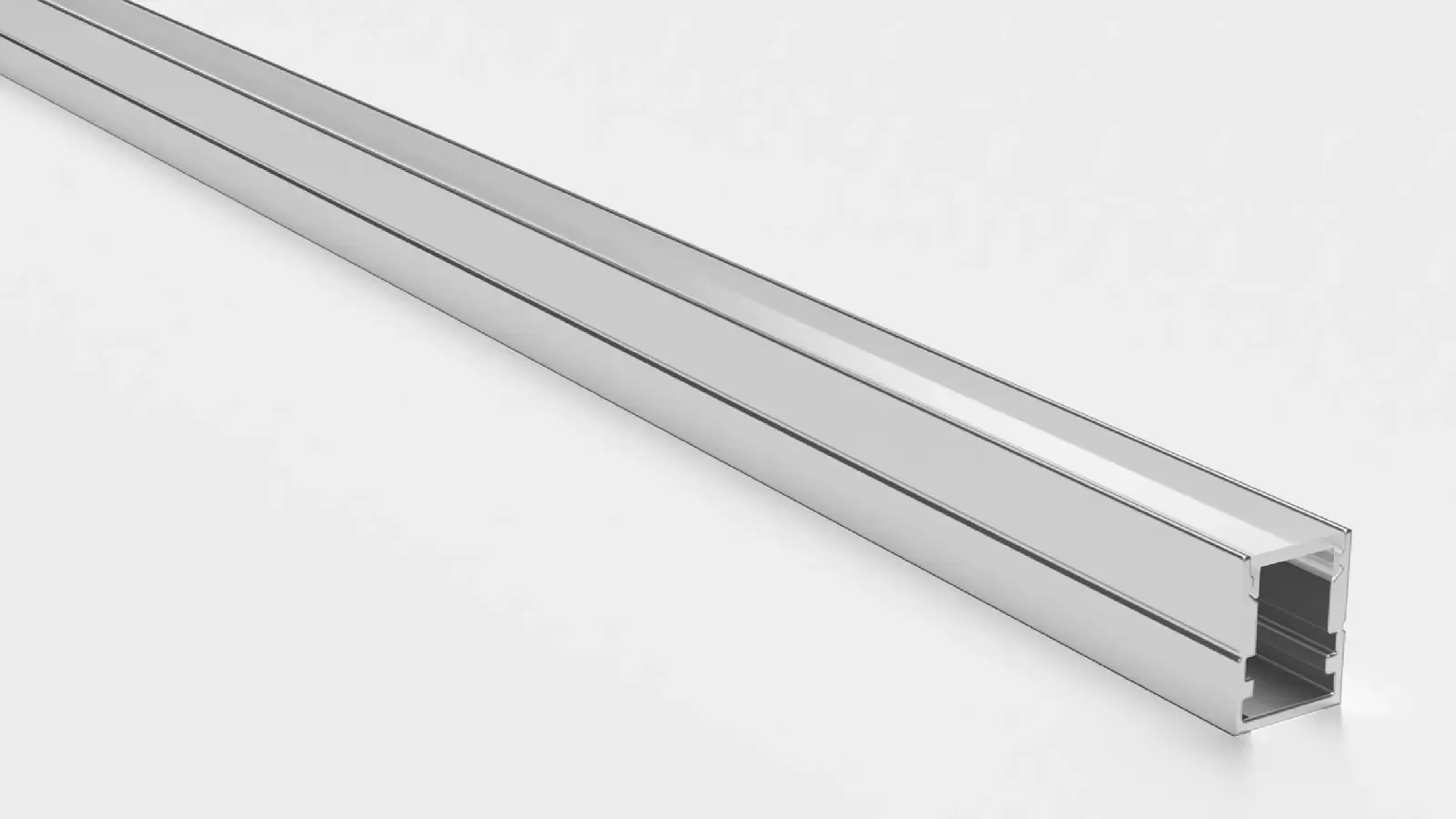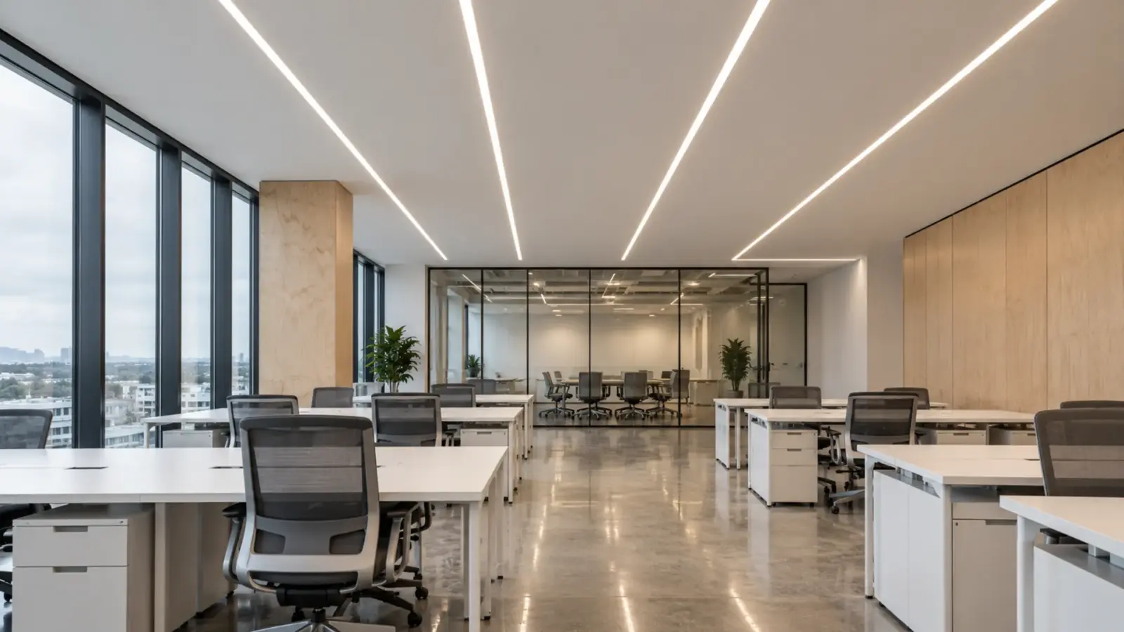
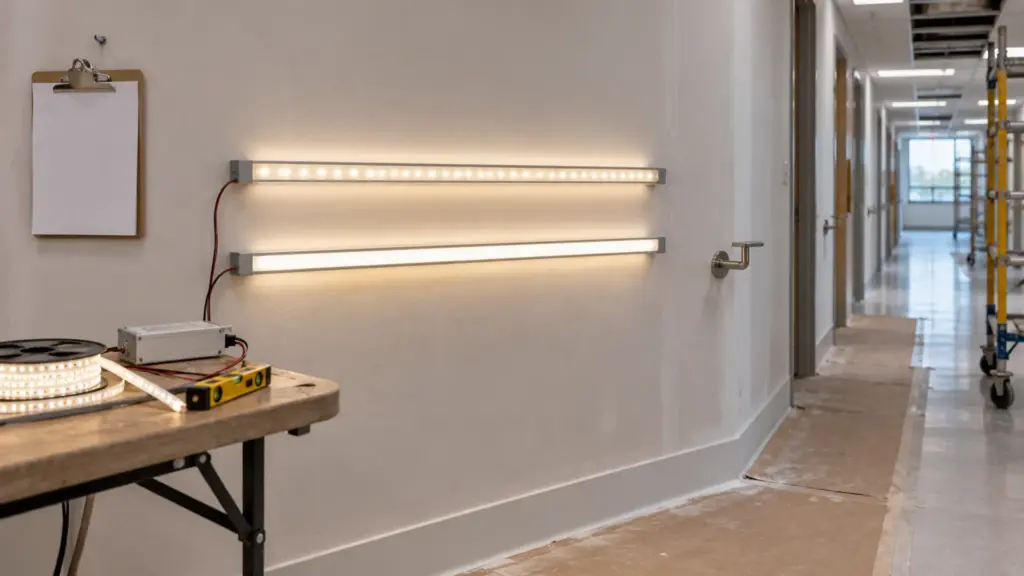
A profile light is LED strip in an aluminum profile behind a diffuser cover. The strip makes the light. The profile holds it, draws off heat and keeps the line straight, and the cover blends the LEDs into one line. So profile light vs LED strip is bare strip against the same strip in a channel.
The term causes trouble on US jobs because it is not US spec language. “Profile light” is how sellers in India and other markets outside the US describe the linear grooves in a false ceiling or the lit line under a shelf. A US drawing would call the same thing an LED channel, an extrusion or a linear fixture, and those are not the same submittal. The sections below answer the questions in the order a contractor usually asks them.
What a Profile Light Is
Strip a profile light down and you find four parts: a length of LED strip, an aluminum channel, a polycarbonate cover, and end caps and clips. According to Orient Electric’s explainer, the profile is a slim aluminum channel topped with a diffuser cover that spreads the light along its length, and Studio Matrx’s design guide describes the same build: an aluminum channel, a diffuser, and the strip inside.
There are two ways to get one. Site-built: the strip, the channel and the cover arrive as separate parts and are assembled on the job or in a shop. Factory-built: the same parts come assembled and sold as a finished linear luminaire, usually with its own listing and photometric file. Sellers use “profile light” for both. On a submittal the difference matters, and we come back to it below.
The words on a drawing translate like this:
| On the drawing or in the email | On a US submittal |
|---|---|
| Profile light, LED profile, aluminium profile | LED channel or aluminum extrusion, plus the strip that goes in it |
| Diffuser | Cover or lens: clear, frosted or opal |
| Profile light sold as one product | Linear fixture, usually listed as a luminaire |
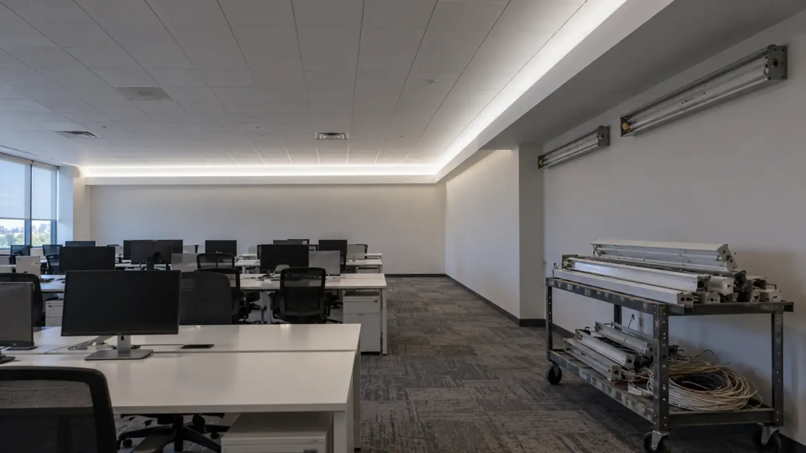
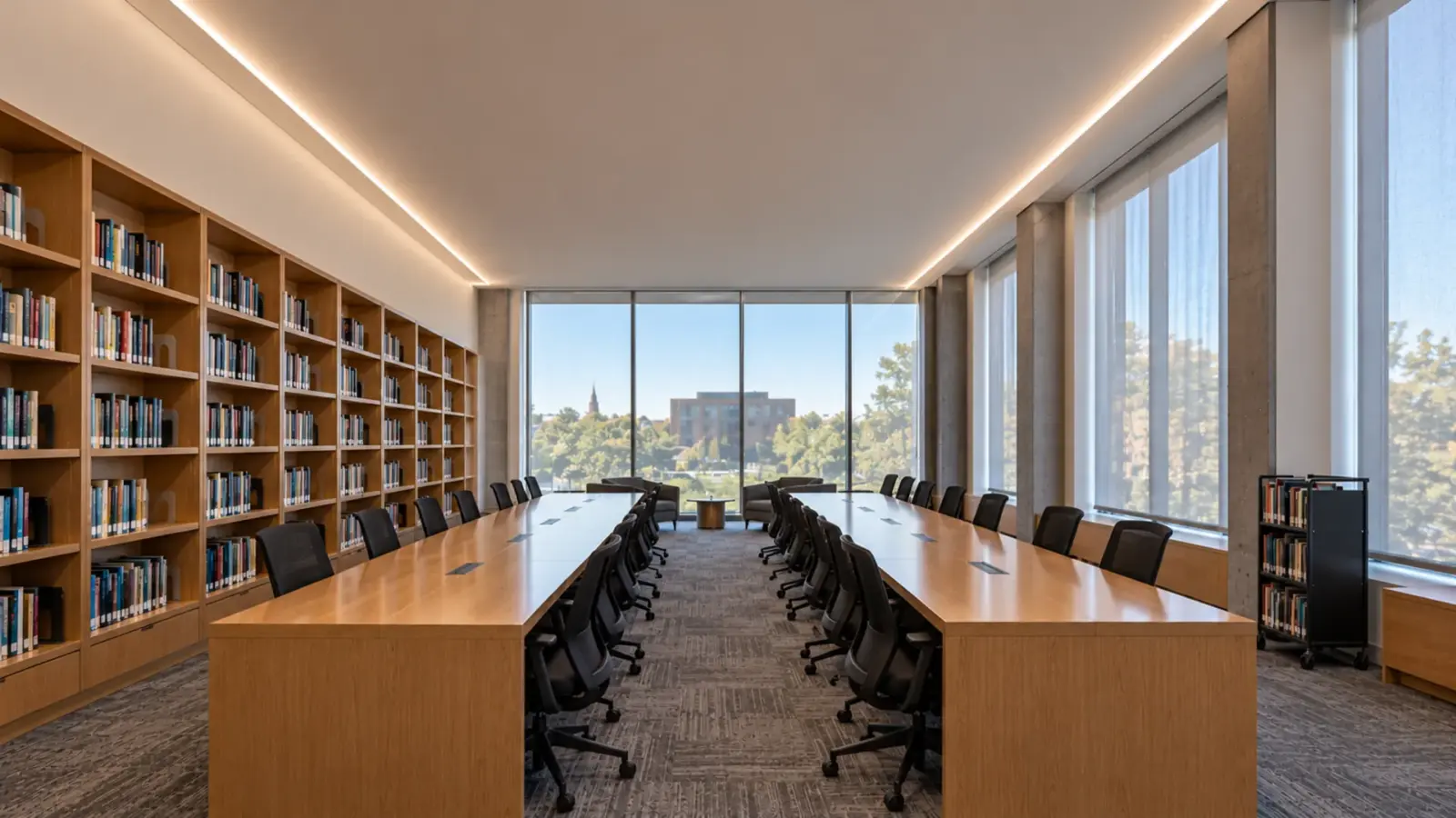
| Concealed profile, false-ceiling groove | Recessed or plaster-in (trimless) channel |
Same Strip, Three Changes: Line, Heat and Mounting
Putting strip into a profile changes three things and leaves the rest alone.
The line. Bare strip shows its LEDs as a row of points, unless it is a dot-free COB or SCOB strip. A cover at the right distance blends them into one line. This is the reason most people specify a profile.
The heat. Aluminum pulls heat out of the strip and spreads it along the run, which is kinder to the adhesive and to the LEDs than a painted wall or a wood shelf. Whether a channel is required at all is a separate question, set by the strip’s own instructions, not by a general code rule; our guide on whether LED tape needs a channel goes through it.
The mounting. A profile gives the strip a straight, rigid base and a way to mount it: surface clips, a recess with a flange, a plaster-in wing, a 45° corner, or cable to hang it from the structure. Bare strip relies on its tape and on the flatness of whatever it is stuck to.
What does not change: the rated color temperature and Color Rendering Index, 0–100: how truthfully the light shows colors next to a reference source. Ra≥90 is the usual bar for interiors., the voltage, the watts per foot and the run length per feed. Those all come from the strip, although a cover can shift how the color reads, so check it on the mockup. A profile light built from a 24V strip is a 24V strip, with the same driver and the same feed plan.
What the Cover Costs: Light Through Clear and Opal
A cover cannot add light; it can only pass part of the strip’s output. On our channels, a PC clear cover passes roughly 90 to 95 percent and leaves the LEDs visible, and a PC opal cover passes roughly 70 to 80 percent and blends them into one line. Applied to strips that list their output per foot:
| Strip | Listed output | Through clear cover (90–95%) | Through opal cover (70–80%) |
|---|---|---|---|
| UT-SFS160-8 (SMD, Ra≥95) | 307–365 lm/ft | 276–346 lm/ft | 214–292 lm/ft |
| UT-CSP-320-N (CSP) | 296–316 lm/ft | 266–300 lm/ft | 207–252 lm/ft |
| UT-CSP-480-N (CSP) | 396–415 lm/ft | 356–394 lm/ft | 277–332 lm/ft |
| UT-SFS160-8-HO (SMD, high output) | 585–702 lm/ft | 526–666 lm/ft | 409–561 lm/ft |
The practical use: size the strip to the light you need after the cover, not before it. If a design calls for about 250 lm/ft out of an opal profile, UT-SFS160-8 can fall short at the low end of its range, while UT-CSP-480-N clears it across its whole range. That is the “size the strip up one step behind opal” rule in numbers. Our guide to clear, frosted and opal covers explains why “frosted” is not a performance figure until someone attaches a number to it.
Depth and Dots
Opal alone does not hide dots. The dots disappear when the distance from the LEDs to the cover is larger than the distance between neighboring LEDs, the pitch rule our guide to LED dots through a diffuser works through with numbers. Pitch is 1,000 mm divided by the LEDs per meter: 60 per meter is 16.7 mm apart, 160 per meter is 6.25 mm.
Vendor rules of thumb are more forgiving than the pitch rule: about 12 to 15 mm of optical depth behind opal for 60 LEDs per meter, about 7 to 10 mm for 120 per meter, and about 3 to 5 mm for COB. Treat the pitch rule as the safe side and the vendor bands as the range to mock up. Optical depth is always less than the profile’s outside height, because the channel floor and the strip take room.
That is why so many “profile lights” in shallow grooves still show beads. A shallow profile is a profile for COB or dense CSP; a deep one such as UT-CH2415, at 24×15 mm with about 14.5 mm of optical depth, is the profile documented for fully diffused, dot-free output with standard-density strip. At 60 per meter it sits on the edge of the pitch rule, so where the line is seen at a steep angle, approve it on a mockup.
Worked the other way: UT-SFS160-8 has 160 LEDs per meter, a 6.25 mm pitch, so it needs more than 6.25 mm between the LED faces and the cover. Check that number against the profile’s optical depth before the cover choice, not after the mockup.
The Parts on the Submittal
A site-built profile light is specified as parts. Each line decides something different:
| Part | Example | What it decides |
|---|---|---|
| Channel | UT-CH2415, 24×15 mm, 2 m or 3 m lengths | Mounting, optical depth, maximum strip width (15 mm here) |
| Cover | PC opal (ships with the channel, with a clear cover) | How much light passes and whether the line reads as one |
| Strip | UT-CSP-480-N | Output, color, CRI, voltage, watts per foot, run per feed |
| End caps and clips | Matching the channel | How the run ends, how it is fixed, where the lead exits |
| Driver | Sized from watts per foot | Load at no more than 80 percent of rating, dimming protocol |
| Run schedule | Lengths by location | Where channels join, where feeds enter, how pieces are cut |
Two details are easy to miss. The strip’s PCB has to sit flat on the channel floor with about 1 mm of clearance, so match the PCB width to the channel’s listed maximum strip width by number. And on larger projects channels can be pre-cut to the run schedule, so each piece arrives labeled for its location instead of being cut on a ladder.
Long grooves are built from several pieces. Channels come in 2 m and 3 m (6.6 and 9.8 ft) lengths, so a 30 ft (9.1 m) groove is at least four pieces and three joints. Show the joints on the run schedule, and remember the channel does not change the strip’s run limit: the feed points still come from the strip. Our LED channels and diffusers page lists every profile’s dimensions and maximum strip width.
Grooves, Coves and Shelves: Picking the Profile
Most photos labeled “profile light” show one of five details. Each has its own profile family:
| Detail | Profile type | Our example | Size, max strip |
|---|---|---|---|
| Lit groove flush in a drywall ceiling or wall | Recessed, trimless plaster-in | UT-CH2020 | 20.2×19.5 mm, 12 mm |
| Line recessed into millwork or a reveal | Recessed, flanged | UT-CH1708 / UT-CH1715 | 17×8 mm, 10 mm / 17×15 mm, 12 mm |
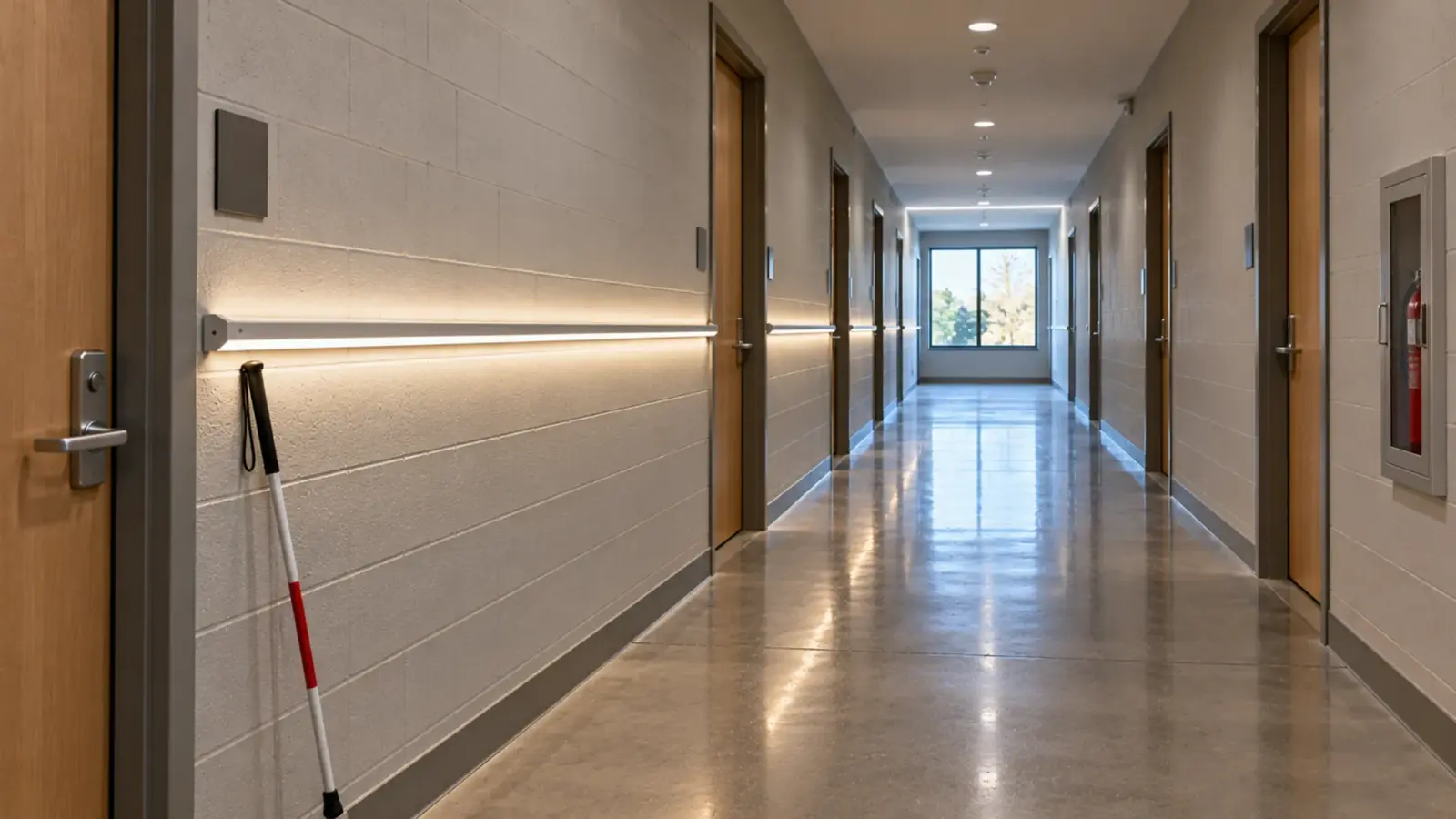
| Under a cabinet or shelf, no cutting | Surface, slim or compact | UT-CH1013 / UT-CH1207 | 13×10 mm, 10 mm / 12×7 mm, 8 mm |
| Visible line that must hide standard-density strip | Surface, deep | UT-CH2415 | 24×15 mm, 15 mm |
| Cove or corner, light aimed out | Corner, 45° | UT-CH1616 | 16×16 mm, 10 mm |
The plaster-in groove is the detail behind most false-ceiling “profile light” photos. Its mounting wings take joint compound, so the channel disappears into the ceiling and only the lit line shows; our guide to trimless channel details in drywall covers the taping and the joints. For a line hung in the room rather than set into it, see our note on suspended linear LED channel. The channel selection guide goes deeper on depth and install order.
Profile Light or Linear Fixture
Here the US vocabulary matters. A site-built profile light is a set of components: a strip, a channel, a cover and a driver, each with its own data. A factory-built linear fixture is one luminaire, usually with its own listing and photometric file. To an inspector and a lighting designer those are different submittals, even when they look identical on the ceiling.
If the drawing says “profile light” and nothing else, ask which one is meant. If a listed linear fixture is specified and a site-built channel system is offered instead, six things move to the installer: the listing, the photometrics, lengths and corners, heat, control and service. Our guide to replacing a linear fixture with strip in a channel works through each one, and Superbrightleds’ comparison of strip and linear light bars draws the same line from the product side.
When Bare Strip Is Enough
A profile is not always worth adding. Bare strip does the job when all of these hold:
- Nobody sees the source. A deep cove with a lip above every sightline, or the back of a sign box, hides the LEDs anyway.
- The surface is metal or the run is low power. A low-wattage strip on a metal shelf rail sheds its heat without a channel; a high-output strip on painted drywall does not.
- The strip’s instructions allow it. Some listed strips call for a heat-conducting mounting; follow them.
- The mounting surface is clean, flat and reachable. Tape that lets go above a finished ceiling is a callback.
When any of these fails, the profile pays for itself in appearance, in a cooler strip and in a mounting that stays put.
Rules of Thumb
A profile light is LED strip in an aluminum channel behind a cover, and every spec decision except the cover and the mounting still belongs to the strip. Size the strip to the light you need after the cover: about 70 to 80 percent through opal. Pick the depth from the LED pitch, not from the cover. Write the channel, the cover, the strip and the driver as separate lines, and say whether the drawing means components or a listed fixture.
The channels, covers and strips named here are in our LED channels and diffusers range, specified together as one system.