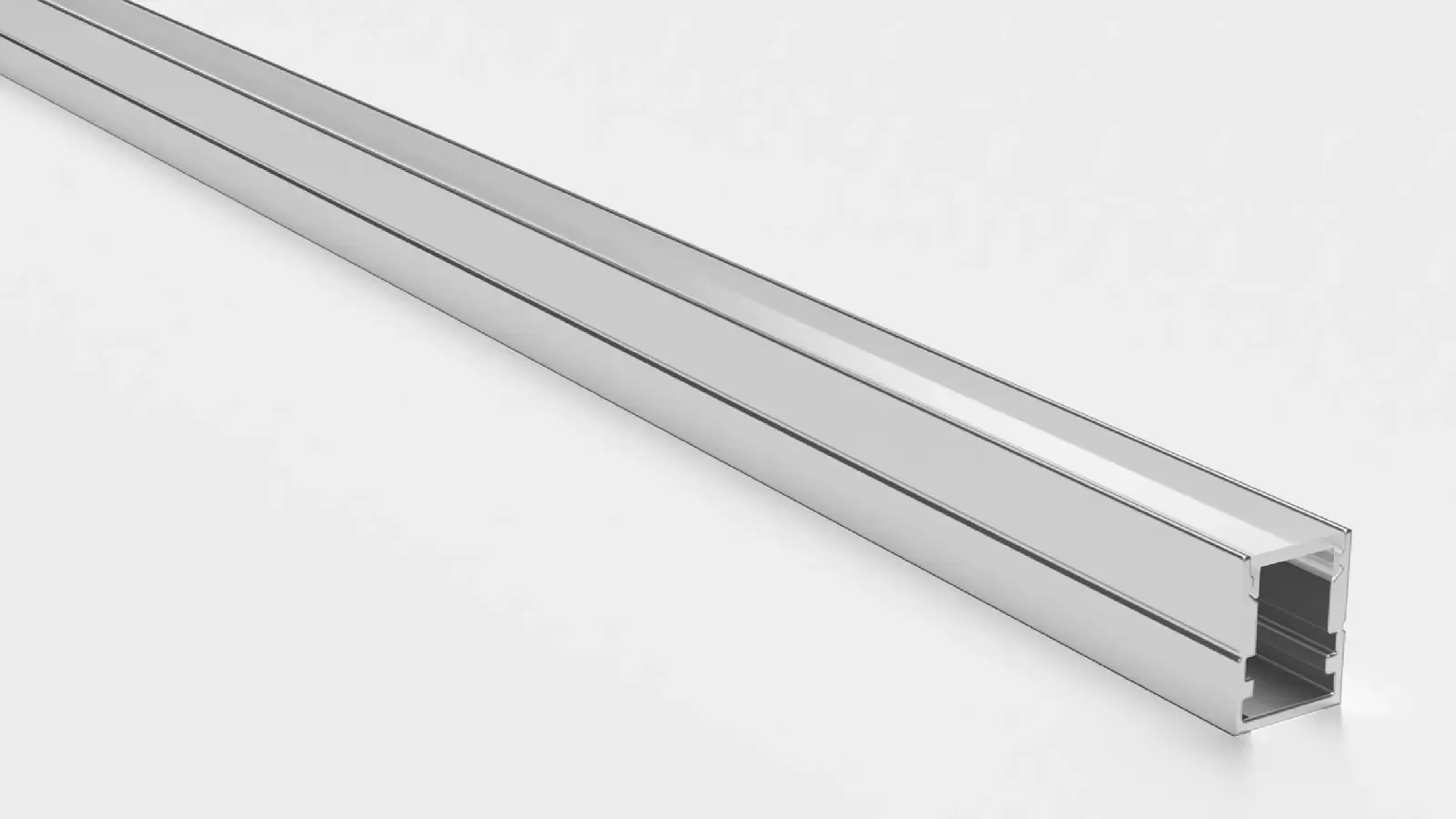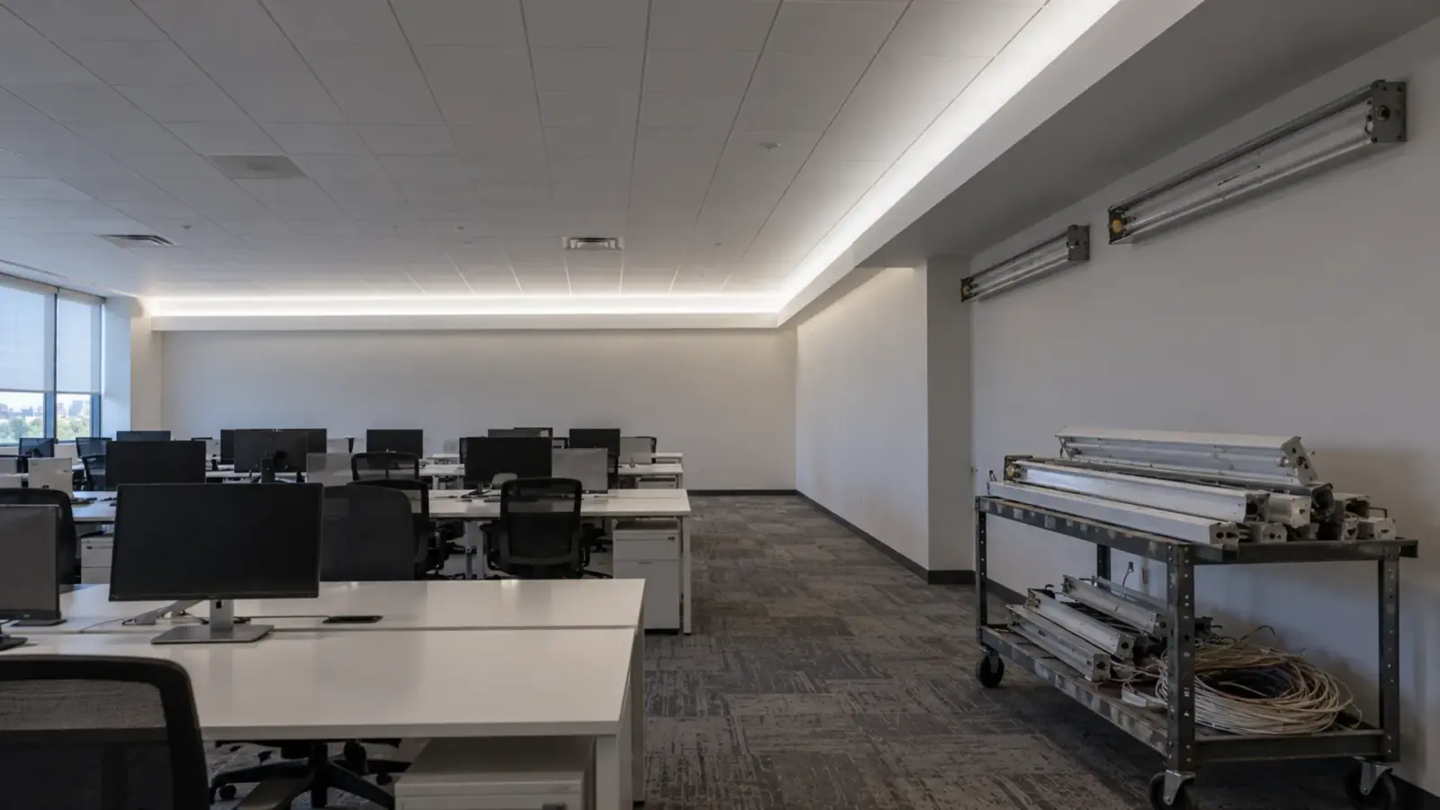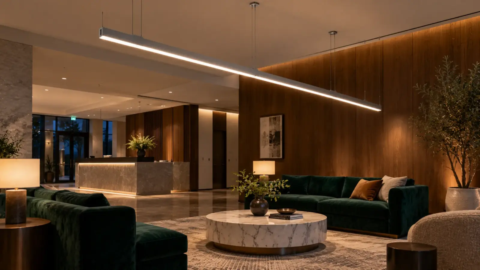
The reflected ceiling plan hangs three 9.8 ft channels end to end over a hotel lobby seating area, with one note: “suspended linear LED, power from above.” Nobody has said what carries the weight, where the hang points go or where the driver sits, and the ceiling over the seating is a finished plaster surface in six weeks.
To hang a linear LED channel, carry it from the building structure on cable at hang points near each end and one in the middle of any length past 5 ft, feed it low-voltage from a remote driver through the end canopies, and level it at every point before trimming the cable. Check sprinkler clearance and the support rules with the AHJ before the ceiling closes.
Choose the Support: Structure, Grid and Reinforcement
A hung channel is a small structural job, and the install sheets we read say so. Inter-lux’s sheets for its suspended linear fixtures call for a qualified electrician, and its October 2025 sheet for a 20 mm linear adds that the contractor is responsible for adequately reinforcing walls and ceilings to support the fixture’s weight, with blocking where necessary. Signify’s sheet for a suspended fixture says to install it in accordance with national and local building and electrical codes.
The NEC adds one rule that matters for grid ceilings. Mike Holt’s EC&M article, reading the 2017 NEC, says section 410.36(B) requires framing members that support luminaires to be fastened to each other and securely attached to the building structure at appropriate intervals, with luminaires fastened by listed screws, bolts, rivets or clips. He adds that the NEC does not require independent support wires for suspended-ceiling luminaires in a non-fire-rated ceiling, but building codes often do. We did not read the 2026 text, so check the adopted edition.
Here is how two manufacturers’ sheets treat the three common ceilings.
| Ceiling | What the sheets do | Check |
|---|---|---|
| Plasterboard, tile or panel | Inter-lux: S20LDL sheet (2015): a 1-1/4 in (32 mm) hole at each suspension point, ceiling thickness up to 1-3/8 in (35 mm), claws locked by captive screws | Thickness, and what sits above the board |
| Suspended T-bar grid | Signify: mounts attach directly to the tee on grid | The grid’s own attachment to the structure |
| Concrete, wood or metal deck | Inter-lux: a plate fixed to the ceiling, and a drilled hole or a conduit for the low-voltage feed | Anchor type for the substrate |
Weight is the number to ask for. Our channels page gives no weight per foot, so get it from the quote for the channel, its cover and the strip, add the cable and canopies, and give the total to whoever checks the structure. EC&M notes that a box may support a luminaire up to 50 lb unless it is listed for the actual weight (314.27(A)(2)). Check each canopy kit: one Inter-lux open-ceiling option hangs the fixture from a junction box cover, so there a box is in the load path. Where the channel hangs on cable from the structure, our reading is that the cables and anchors carry it, and the box carries only the feed.
Our channels page lists no suspension hardware, so the cable, the canopy and the anchor come with the quote or from the installer’s kit. The channel page’s own limit is the clips: every kit ships with two end caps and mounting clips at 19.69 in (500 mm) spacing for fixing to a surface, not for hanging.
Hang Points: Where and How Many
Inter-lux’s sheet shows the pattern for its own housing: suspension points 3 in from each end for fixtures up to 60 in, and a center suspension for anything longer. That is one maker’s pattern for one housing, so treat it as an illustration. A channel’s stiffness, its weight with the strip and cover, and the cable all change the answer, and the installer or the structural engineer sets it.
Our channels come in 6.6 ft (2 m) or 9.8 ft (3 m) lengths, both past 60 in. A worked case with assumed numbers: three 9.8 ft lengths of UT-CH3020 hung end to end make a 29.4 ft run. Assume a point at each channel end, shared at the two joints, and one at each center: four end and joint points and three center points, seven in all. Inter-lux’s pattern of 3 in from each end of every fixture plus a center would give nine points for three lengths, with two points 6 in apart at each joint, so a shared joint point is a layout choice for the engineer to confirm.
Here is the assumed plan for the run, with a shared point at each joint.
| Point | Where | Carries |
|---|---|---|
| 1 | First end, 3 in in | End of length 1 and its feed cable |
| 2 | Center of length 1 | The middle span |
| 3 | Joint 1 | Adjoining ends of lengths 1 and 2 |
| 4 | Center of length 2 | The middle span |
| 5 | Joint 2 | Adjoining ends of lengths 2 and 3 |
| 6 | Center of length 3 | The middle span |
| 7 | Far end, 3 in in | End of length 3 |
Mark every point on the plan with its distance from the nearest channel end and the structure it attaches to, and send the plan to the sprinkler designer and the ceiling sub together. A point that falls on a duct or a beam moves, and the channel’s pattern moves with it.
The Feed: Driver Above, Cable Through the Canopy
A suspended channel carries 24V strip, so the power comes from a driver, and the driver does not hang with the channel. Put it above the ceiling or in a closet and run low-voltage cable down through a canopy. Inter-lux’s sheet routes the low-voltage feed from the fixture through the mount to the driver, and LEDSupply notes that some canopies carry suspension only while others also pass power. Use a strain relief wherever a cord passes through a canopy, as LEDSupply advises. Our remote driver guide shows why the cable length limits the distance.
Take the worked run. UT-C480-8 is a 3.2 W/ft COB strip, so 29.4 ft loads 94 W (29.4 × 3.2). Our spec table limits one feed to 16 ft, and our drivers page keeps the load at or below 80% of a driver’s rating. A 60 W Class 2 driver carries 48 W, which is 15 ft of that strip. One feed and one driver per 9.8 ft length gives 31.4 W each, inside both limits, and each length’s end canopy carries its own cable. That is three feeds and three drivers; our voltage drop guide explains why a single feed to the far end would dim it.
The cable that comes down is a wiring-method question. Our in-wall wiring guide covers which cable can run where, and a hot ceiling void changes the driver size; see driver derating in enclosed spaces.
Level Before You Trim
Install the ceiling mounts and the vertical cables first, then raise the channel. Signify’s sheet has two people raise the first fixture, insert the aircraft cable into the adjusters at each end, and level before moving on, and it hangs and joins the following fixtures one at a time. Inter-lux’s S20LDL sheet sets the cable length at each end and snugs a set screw in the cable restrainer, then installs the center suspension on a long fixture, levels, and trims the cable at that point. Signify’s sheet trims the cable below its adjuster as it hangs and levels afterward with the adjuster’s fastener. The sequences differ with the hardware, so follow the kit’s sheet, but the principle holds: do not lock a point until the channel reads level, because a set-screw point locked early has to be released and reset.
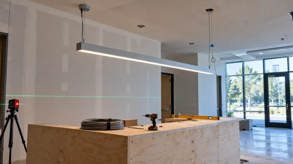
In order, the steps are these.
- Mark every hang point on the ceiling from the plan and check each against ducts, beams and sprinkler heads.
- Fix the anchors or ceiling plates for the substrate, and hang the cables with spare length.
- Route the low-voltage feed through each end canopy with its strain relief and land it on the driver above the ceiling.
- Raise the first channel with two people, fix both ends at the adjusters and level it.
- Lock each point only after the level reads true, trim where the kit’s sheet says, then hang the next length and check the joint against the first.
Joints are where a hung run shows its faults. Two channels hung at slightly different heights leave a step at the joint, and a gap leaves a dark break in the line. Our channels page lists no coupler, so ask for the joint detail at quote, and mock up one joint before the run. Where a length must be cut, the channel cuts with a miter saw and a non-ferrous blade and the end caps re-seat; our guide to cutting and connecting strip covers the strip side.
Light and Cover: What the Eye Sees From Below
A hung channel is seen from below and at close range, which is where dots show. A clear cover leaves the LEDs visible, and an opal cover trades output for one continuous line; our guide to clear, frosted and opal covers covers the choice by depth, and our channel selection guide covers the profile. Heat is a second reason to choose carefully: a strip’s heat still goes into the aluminum, whatever hangs around it, and our thermal performance guide covers matching strip power to the profile.
Sprinklers, Detectors and Plenum
A channel that hangs below the ceiling can sit at or below a sprinkler head’s deflector. Whether that blocks the spray is for the sprinkler designer and the AHJ to decide, so send the designer the elevation of the channel’s lowest point, its width and its length before the points are fixed. Our ceiling cloud guide covers keeping the strip clear of pipes and ducts at a cloud edge.
Checks Before the Channel Goes Up
- The support for each ceiling type, and any reinforcement the sheet or the engineer asks for, agreed in writing.
- Every hang point marked on the plan, clear of ducts, beams and sprinkler heads.
- One driver per feed, each load at or below 80% of the driver rating and each feed within its run limit.
- Cable and strain relief at every canopy that passes power.
- The leveling order set from the kit’s sheet: hang, level, then lock each point.
- One joint mocked up before the run.
The channel sizes above are in our LED channels and diffusers range, with the strip loads taken from the COB spec table.