A 16 ft run of UT-C480-8 draws about 4.3 A at 12V, and the connector at the feed point carries every amp of it. At 24V the same run draws 2.1 A, and the same joint makes about a quarter of the heat.
An LED strip connector gets hot for one of two reasons: too much current for its rating, or too much resistance in the contact. Heat that is the same at every joint points to the first. One joint hotter than its twins points to the second. Check the current at the feed first, then the joint, and do not tape over either.
Heat Is Current Squared: Why the Feed Joint Fails First
A joint is a short stretch of resistance in series with the strip. The heat it makes is the current squared times that resistance, so doubling the current quadruples the heat from the same joint.
The feed joint carries the whole run, which makes it the highest-current joint on the strip. Our strip-to-strip, wire-to-strip and strip-wire-strip connectors and our PCB corner connector are rated 5 A. Here is the current at the feed for a full single-feed run, from the watts per foot in our spec tables.
| Strip and run | Load | At 24V | At 12V |
|---|---|---|---|
| UT-C320-8, 16 ft (5 m) | 38.4 W | 1.6 A, 32% of 5 A | 3.2 A, 64% |
| UT-C480-8, 16 ft (5 m) | 51.2 W | 2.1 A, 43% | 4.3 A, 85% |
| UT-S2835-240, 16 ft (5 m) | 107 W | 4.5 A, 89% | not offered at 12V |
| UT-C1600-30, 10 ft (3 m) | 122 W | 5.1 A, 102% | not offered at 12V |
Two rows matter most. Moving UT-C480-8 from 24V to 12V takes the feed joint from 43% to 85% of its rating and makes about four times the heat. The last row is already over the rating, and no connector on our table fits a 30 mm strip, so that joint is soldered or the run is split. Our connector guide covers choosing a connector for the current, and our 12V, 24V and 48V comparison covers the voltage choice.
A run at its per-feed limit is also a joint at its highest load. Our spec tables set a per-feed run limit, and the feed joint sits where all of that current enters. Feeding the run from both ends changes the numbers. With both ends fed from the same supply on equal leads, the current splits about evenly, so the 12V UT-C480-8 run above puts about 2.1 A through each feed joint. That is the 24V single-feed figure, and about a quarter of the heat per joint.
What a Bench Test Shows
We do not publish heat tests of our connectors, so here is someone else’s. A builder posting as teardownit on Hackaday.io in May 2023 hung connectors in air, ran set currents for 30 minutes each and read them with a thermal imager. A solderless strip connector rated 5 A read 114°F at 5 A, 199°F at 7.5 A and 297°F at 10 A, with the case still intact at 10 A. At 20 A it began to melt and smoke. A 3 A plug-and-socket pair in the same test melted at 15 A.
The page gives no ambient temperature, and it tests parts that are not ours, so use the shape and not the numbers. Up to 10 A the heat climbed faster than the current did, and the failure came at several times the rating, not just above it. Retail clips are often rated somewhere between 3 A and 5.5 A, as listings from Super Bright LEDs and HitLights show, so the rating on the box is the number to read, and a rating is a limit to stay under, not a load to aim for.
The test also pins down where the heat sits. On the strip connector it concentrated “in the areas where the connector contacts the wires,” not at the teeth that pierce the strip. That fits a contact problem more than a strip problem.
Find the Cause: Current or Contact
Picture a typical hospital corridor job. A technician opens the cove lid after a night-shift report of a warm plastic smell, and finds six feed joints along the corridor. Five are warm and evenly so. One is clearly hotter than the rest. Those are two different problems on one ceiling: the five point to current or a hot closed channel, and the sixth points to a contact.
VIOX Electric’s guide to terminal block overheating is about control panels, not strip, but its logic carries over. A localized hotspot at one termination usually points to a connection-resistance problem, and uniform heating across terminals and conductors usually points to overload or undersizing. Its cycle is the one a bad strip joint follows: a poor connection raises resistance, which adds heat, which causes oxidation or mechanical damage, which raises resistance again.
VIOX adds two cautions that apply on a ceiling too. Do not touch, tighten or move a suspected hot connection while it is energized, so switch off first. And there is no universal temperature limit for every terminal, so compare joints with each other and with the datasheet instead of with a fixed number.
| What you see | Likely cause | Test | Fix |
|---|---|---|---|
| Every joint on the run warm, housings evenly hot | Current near or over the rating, or a hot closed channel | Clamp meter on the feed lead; compare with the 5 A rating | Split the run, feed both ends, or move to 24V |
| One joint hotter than its twins | High contact resistance: clip not fully seated, dirty or oxidized pad, weak solder | Thermal imager or IR thermometer across identical joints; millivolt drop across the joint under load | Remake that joint |
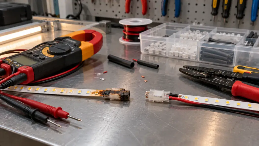
| Brown or lifted copper pad, softened housing | The joint has already overheated | Visual check, power off | Cut back to the next cut mark and make a new joint |
| Warm feed and a dim far end | Run too long for one feed | Our voltage drop guide | Add a feed |
Two measuring notes. Use a clamp meter that reads DC, because an AC-only clamp reads nothing on a 24V DC feed lead. And read the plastic housing, not bare metal, with an IR thermometer, since shiny copper and aluminum can read low. A joint can be warm and fine, so the point of comparing is to find the outlier, not to condemn every warm one.
The millivolt test is the cheap one. With the strip at full output, put a meter across a joint. A drop of 0.2 V at 4.3 A is about 0.9 W (0.2 × 4.3) in a part the size of a fingernail. Compare it with the joint next to it; the value is for comparing, not an acceptance limit.
Fixes That Hold
The usual fix is another clip. It fails when the cause was current, because the new clip carries the same amps. The right fix follows the cause.
- A loose or dirty contact: with power off, cut back to clean copper at the next cut mark and make a new joint. Our guide to cutting and connecting strip covers the cut points.
- An overloaded joint: split the run into more feeds, within the per-feed run limit in the spec table, feed from both ends, or raise the voltage, since 12V to 24V halves the current for the same watts.
- A load over the connector’s rating: solder the joint, as our connector guide advises above 5 A, or split the run so each feed stays under it. A soldered joint has its own failure: a cold joint is a contact problem again, with the same one-hot-joint signature, and too much iron time lifts the pad. Solder pad and wire separately, keep the iron on the joint briefly, and practise on an offcut first.
- A thin or long lead: the wire into the connector should be the gauge the connector is made for. A lead that runs warm along its whole length points to the wire, not the contact, and the fix is heavier wire or a shorter run.
- A hot closed channel: heat in the channel adds to the joint’s own. Our guide to channel thermal performance covers matching strip power to the profile.
Nothing on that list is tightening a live terminal or wrapping a hot joint and closing the ceiling.
Prevent the repeat at design. Put the feed current and the connector’s rating on the run schematic for every feed, so a reviewer sees 85% before the order and not after the smell. A 12V run of high-output strip is the first place to look, because it needs twice the current of the same run at 24V. Where the strip comes in only one voltage, the lever is the number of feeds.
On a Commercial Job: Where the Heat Hides
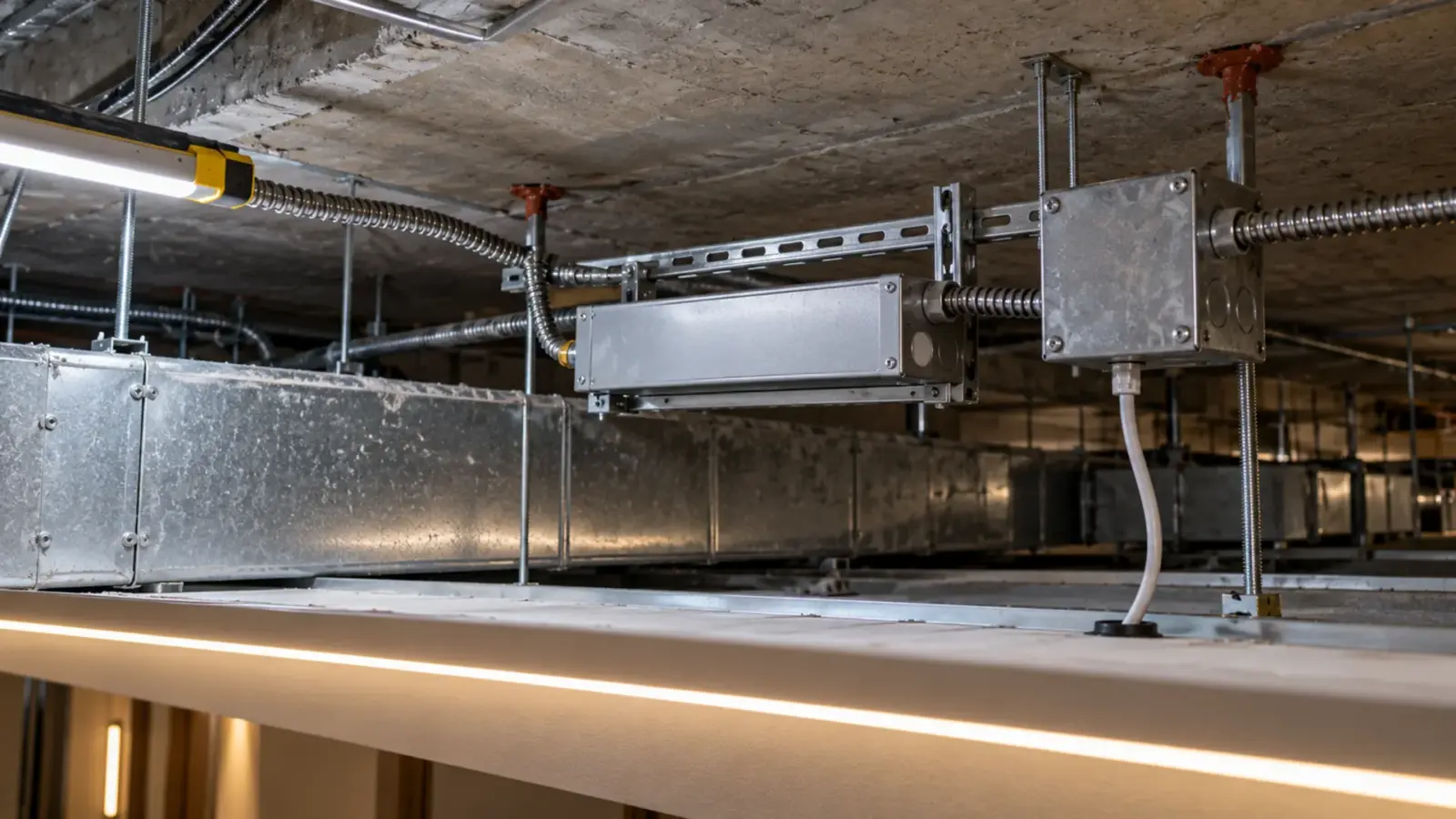
A joint inside a channel, a cove or a millwork cavity gives no warning until it fails, and by then the ceiling is closed. Our fire hazard guide puts joints and drivers ahead of the tape as the places jobs go wrong, and our strip troubleshooting guide starts at the driver terminals. A feed joint is the next place to look.
The moment to catch it is commissioning, before the ceiling closes, with the strip at full output. Heat is not the same at every joint, so one reading at one joint tells you little; read every feed and compare. Our commissioning guide lists the handover steps; the joint checks below belong in them, and a feed joint left out of reach belongs on the punch list.
If a joint does melt after handover, record what you measured before anything is removed: the current at the feed, the connector model, the strip model and a photo of the joint in place. Our warranty claim guide lists what to document, and our maintenance plan guide shows how a run register keeps each feed’s current and location on file for the next visit.
Joint Checks at Handover
- Current at each feed with a clamp meter, against the connector’s rating, with the margin noted.
- A thermal scan or IR reading of every feed joint after the strip has run at full output for a while, comparing identical joints.
- The millivolt drop across any joint that reads warmer than its twins.
- Any joint over 5 A soldered or split, and 12V runs checked first.
- Every feed joint marked on the plan and reachable without opening a finished ceiling.
The connector ratings and run limits above are in our drivers, controllers and connectors page and the strip spec tables.