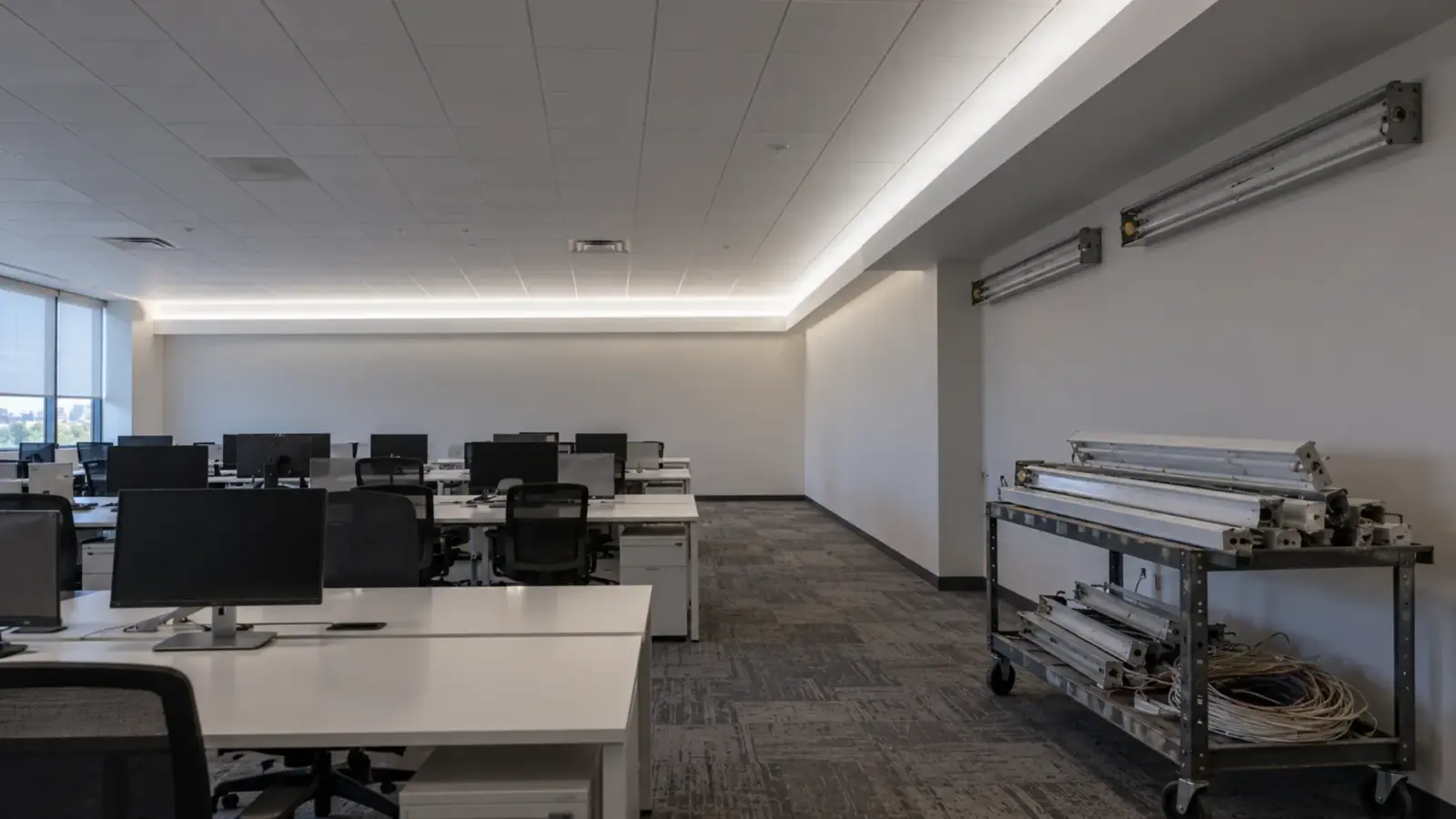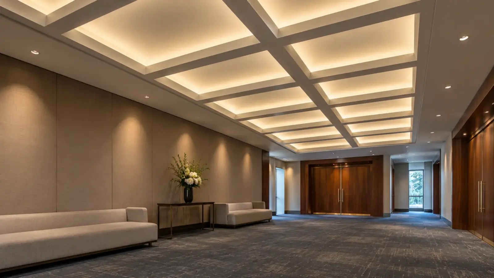
The reflected ceiling plan shows a six-by-eight grid of 4 ft square coffers over a hotel pre-function space, with one note: “LED cove by electrical.” On a typical job like this, that note means 48 coffers, 192 inside corners, 768 ft of coffer perimeter and no instruction on where the drivers go.
To light a coffered ceiling with LED strip, mount dot-free strip on a ledge inside each coffer, aimed up at the panel, with the ledge doing the hiding, and run the power through the beams to drivers that stay reachable. At 4 ft square and lit on all four sides, one coffer carries about 40 to 50 W of strip, so count drivers per coffer, not per room.
The Pattern: Ledge, Lip and Gap
Our cove page describes cove lighting as a strip hidden in a ledge or recess and aimed at a surface, so the room is lit by the surface rather than the source. A coffer repeats that pattern in a closed rectangle. Liam Cope’s coffered-ceiling guide for Engineer Fix describes strips run along the interior perimeter of the coffer beams, directing light up onto the flat central panel, housed in an aluminum profile with the source hidden behind the molding.
Three parts decide the look. The ledge is a shelf projecting from the beam’s inner face with the channel on top. The lip is whatever stands between the channel and the eye. The gap is the vertical distance from the channel to the panel, and it decides whether the panel shows an even wash or a row of bright arcs.
In a coffer the shelf does most of the hiding. From the floor, the ledge normally screens the channel: anyone standing below the ledge plane sees only its underside. The exceptions are viewers above the ledge, such as a mezzanine or gallery that looks across at the ceiling. Draw those sightlines before anything else; our cove lighting page covers lip height for them.
Finish matters as much as geometry. The panel is the lit surface, so it should be matte, because a glossy panel mirrors the strip. Say on the plan whether the owner wants the grid read by lit panels, lit beam faces or both, because that changes how high the strip sits and how it is aimed.
Depth Sets the Gap
Our cove page treats 4 in (100 mm) as the minimum setback, meaning the gap from strip to surface, with dot-free COB or a diffuser when the strip sits closer. In a coffer the gap is what is left of the depth: coffer depth, minus the height of the ledge top above the beam’s lower edge, minus the channel height.
Here is that arithmetic with a UT-CH2415 surface channel (24×15 mm, 0.59 in tall) and an assumed ledge top 1 in above the beam’s lower edge.
| Coffer depth | Gap left | Reading |
|---|---|---|
| 4 in | 2.4 in | Under our 4 in minimum: dot-free COB or an opal cover, and a mockup |
| 6 in | 4.4 in | At the minimum |
| 8 in | 6.4 in | Comfortable |
| 12 in | 10.4 in | Most freedom; high-efficacy SMD works on a matte panel |
When the section is tight, aim helps as well as distance. Our cove page notes that a strip lying flat throws most of its light straight up, and that tilting it toward the joint spreads the wash further; in a coffer that is the beam-panel joint. The 16×16 mm UT-CH1616 corner channel aims the strip at 45° and takes strip up to 10 mm wide, which suits a ledge that meets the beam face at a 90° corner. Mock up the shallowest coffer first, because the rest of the grid is easier than the worst case.
A shallow coffer is the common trouble. The fix is the strip, not a smaller channel: dot-free COB LED strip hides the individual sources at a short gap, as our cove page advises. A glossy panel mirrors the strip, and our cove page calls for COB wherever the lit surface is glossy. Our COB vs SMD guide for coves covers which strip suits which gap, and our guide to dots showing through a diffuser covers the cure when they appear anyway.
Size the ledge for the channel, not the bare strip, and leave room behind the channel for the connector and a hand. Our LED channels and diffusers range lists the sizes.
Power Per Coffer: Count Watts, Not Rooms
A ceiling with one cove around the room can run on a driver or two. A grid cannot, because every coffer is its own loop. Our drivers page gives the rule: multiply watts per foot by the run length for every run on the supply, keep the total at or below 80% of the driver’s rating, and let the datasheet govern.
A 4 ft square coffer lit on all four sides carries about 16 ft of strip. Here is the load by strip and by how many sides are lit, against a 60 W driver such as UT-D60-24-C2-010, which leaves 48 W at 80%.
| Strip | W/ft | Lit sides | Strip per coffer | Watts per coffer | Coffers per 60 W driver |
|---|---|---|---|---|---|
| UT-S2835-128-HE | 2.9 | four | 16 ft | 46.4 | 1 |
| UT-S2835-128-HE | 2.9 | two opposite | 8 ft | 23.2 | 2 |
| UT-C480-8 | 3.2 | four | 16 ft | 51.2 | 0, over 48 W |
| UT-C480-8 | 3.2 | two opposite | 8 ft | 25.6 | 1 |
| UT-C320-8 | 2.4 | four | 16 ft | 38.4 | 1 |
| UT-C320-8 | 2.4 | two opposite | 8 ft | 19.2 | 2 |
The 48-coffer grid becomes 24 to 48 drivers for the other five rows, and more than 48 for four-sided UT-C480-8, whose 51.2 W is over the limit. A 96 W model such as UT-D96-24-010 leaves 76.8 W at 80%, which carries one four-sided UT-C480-8 coffer or two two-sided ones. Lighting two opposite sides halves the strip and driver load, and a mockup shows whether the panel still glows evenly across its width.
Add the grid up before the panel schedule does. Forty-eight four-sided coffers of UT-S2835-128-HE come to about 2.2 kW of strip (48 × 46.4 W), and lighting two sides of each halves that to about 1.1 kW. At 120 V the first is roughly 18.5 A before driver losses, so the circuit count and the inrush of 24 to 48 drivers belong on the electrical drawings, not only in the lighting notes. Our inrush guide covers breaker counts, and our power supply sizing guide covers the arithmetic.
Our spec tables list 16 ft (5 m) per feed for these models. A 16 ft coffer perimeter sits at that limit before the corners and leads, so feed each coffer at two points or split it into two runs; our voltage drop guide explains why the far end dims.
Corners and Joints: 192 of Them
Every coffer has four inside corners, so the grid has 192, and a coffer lit on all four sides turns the strip at every one. Light two opposite sides and the corner joints disappear, at the cost of two darker sides. A standard strip bends up and down, not sideways, as our special-form strip guide explains. On the flat of a shelf, each corner takes a cut and a joint: a PCB corner connector, a wired jumper, a soldered joint, or an S-bend strip that bends in its own plane. Our connector guide covers which fits the current and the location, and our curved cove guide covers what bends and what kinks.
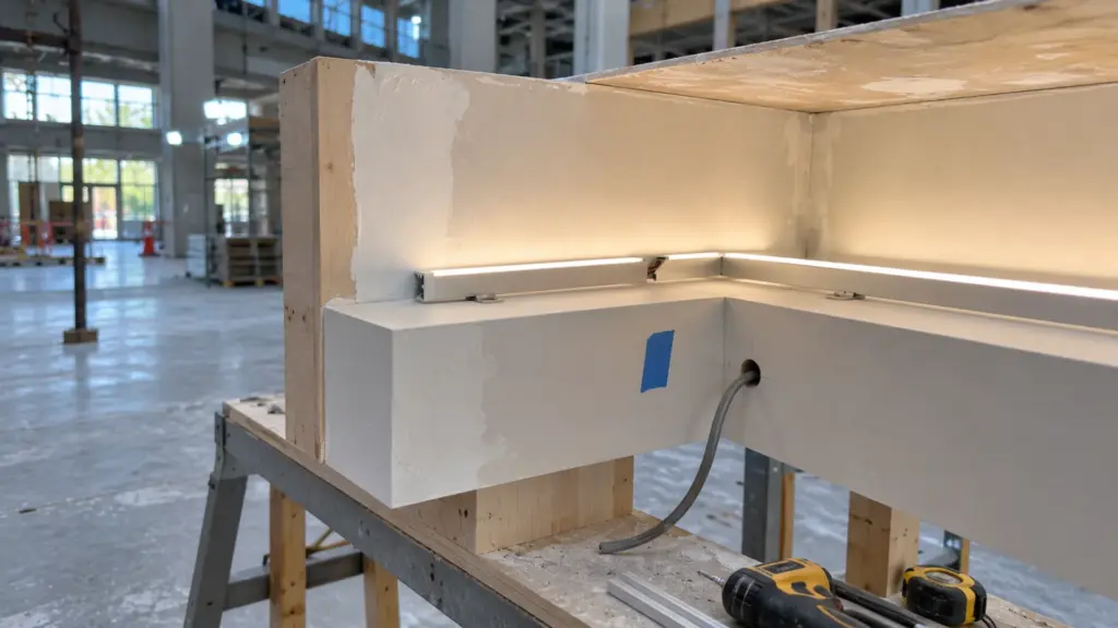
Each joint is a place a crew can leave a dark corner, so cut only at the marked cut points, plan every length in whole cut multiples to end at a corner, and keep joints out of the middle of a side. Number the coffers on the plan and the strip lengths to match.
Count the connection points too. Feed each four-sided coffer at two points and the grid has 96 feed connections as well as 192 corners, 288 points to number, test and leave reachable. A coffer that goes dark should lead the crew from the plan to one strip length and one driver, and the numbering is what makes that possible.
Drivers and Access
A driver sealed above a finished panel turns a repair into a ceiling repair, and 24 or 48 hatches are not a plan. Engineer Fix puts the driver in an accessible location such as an electrical closet and runs low-voltage cable through the hollow of the beams, with access to every junction and splice.
The practical layout follows from that. Put the drivers together in a closet or an above-ceiling zone with an access panel, run low-voltage cable from there through the beams to each coffer, with the wiring method confirmed with the AHJ, and keep the connection between cable and strip reachable from below, for example behind a removable length of the channel cover. Our remote driver guide shows why the distance is limited by the cable, and our in-wall wiring guide covers which cable can run where. A hot ceiling void changes the driver size; see driver derating in enclosed spaces.
The beams are usually framed by the ceiling sub, not the electrician, so the ledge height, the ledge width and the cable holes have to be on the framing drawing before the board goes up. Give the sub the channel model and its size; our trimless channel guide covers the same hand-off for drywall.
Zone the grid before wiring it. Grouping coffers by driver gives a zone map: a ballroom may want each bay on its own zone and a corridor all together, and the map decides how many drivers and control pairs the beams carry. For dimming, a 0-10V driver such as UT-D60-24-C2-010 lets one wall panel set the whole zone. Event spaces that add color scenes belong to our ballroom cove guide.
Checks Before the Ceiling Closes
- Build one full-scale coffer with the real finish and the real strip, light it, dim it, and approve it before the order; our mockup approval guide lists what to look at.
- The gap against the coffer depth, and a note on the strip type where it is under 4 in.
- Watts per coffer and coffers per driver on the schedule, at or below 80% of the driver rating.
- The corner joints counted (192 when every side is lit), each with a method, and every length cut to end at a corner.
- Driver location, cable routes and access panels marked, with each coffer’s cable labeled to its driver.
- Sprinkler heads and smoke detectors on the same plan; a beam or lip near a head goes to the sprinkler designer.
The strip, channel and driver models named here are in our LED channels and diffusers and COB LED strip ranges, with the coffer loads above taken from their spec tables.