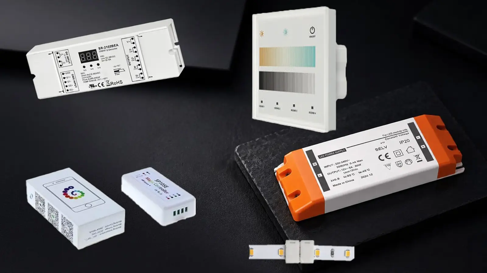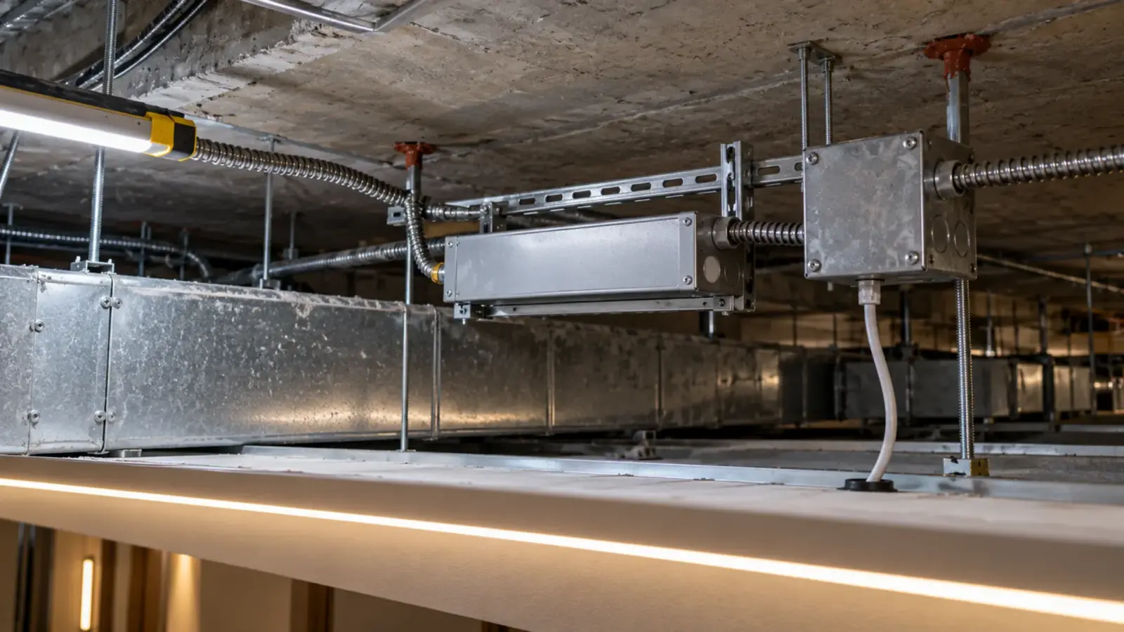
LED drivers trip breakers at switch-on because each driver’s input capacitors charge in the first millisecond, pulling a current spike many times its running current. On a shared circuit the spikes from every driver arrive together, and the breaker’s instant-trip element sees one large pulse even though the steady load is well inside its rating.
A lighting circuit that carries its drivers all day can still trip the breaker the moment it is switched on. That is why the usual fixes, a bigger breaker or a recount of the watts, either do nothing or create a new problem. The load calculation is not wrong. It answers a different question. This article explains what happens in that first millisecond, how to count drivers per breaker when inrush sets the limit, and which fixes work, cheapest first.
The Trip Happens in the First Millisecond
Every switch-mode LED driver has bulk capacitors on its input. When power arrives they are empty, and for a moment they behave almost like a short circuit until they charge. According to Appleton’s technical article on inrush, that charge can draw around 40 to 70 A and lasts only 1 to 2 milliseconds, long enough to trip the breaker on the circuit.
A thermal-magnetic breaker has two ways to trip. The thermal element responds to sustained overload and does not care about a 2 ms spike. The magnetic element responds to a high instantaneous current, the kind a short circuit produces, and it cannot tell a short from thirty drivers charging at once. That element is what opens the circuit.
Two details make the trips look random on site:
- The point on the wave. According to Eaton’s guidance on lighting breakers, peak inrush rises with the phase angle at switch-on. A switch closed near the peak of the AC wave gives a larger spike than one closed near zero. One UK electrician described a Type B breaker that tripped about one switch-on in four, which is exactly what a point-on-wave effect looks like.
- Cold or warm start. A driver that was switched off a second ago may still hold some charge. The first switch-on of the morning is often the one that trips.
So a circuit can pass its test, run all day, and trip at 7 a.m. Nothing is faulty. The circuit was laid out by watts, and watts do not describe the first millisecond.
Why the Load Calculation Says the Circuit Is Fine
Take a 20 A, 120 V lighting circuit. Lighting is a continuous load, so it is planned at 80 percent of the breaker rating: 16 A, or 1,920 VA.
Now fill it with 60 W Class 2 drivers, each loaded to 48 W of strip, which keeps them at the usual 80 percent. Assume a driver efficiency of about 88 percent (the datasheet gives the real figure). Each driver then draws about 55 W from the line, roughly 0.46 A at 120 V. By the load calculation the circuit takes about 34 drivers.
Then look at the switch-on. If each driver’s inrush peak were 30 A, an example figure and not a datasheet value, thirty-four drivers switched together would ask for a peak in the hundreds of amps for about a millisecond. Wiring resistance and the source limit how much of that actually flows, so the real peak is lower than the simple sum, but it can still sit far above what the breaker’s magnetic element tolerates.
The steady-state number and the switch-on number are two different checks. According to Acuity’s eldoLED guidance, the first check is the steady current and the second is inrush, and drivers from some makers have high inrush even below 100 W, so the inrush specification should always be looked up rather than assumed. For the steady-state side of driver sizing, our guide on how to size an LED strip power supply walks through the 80 percent rule.
Reading Inrush on a Driver Datasheet
A driver datasheet that takes inrush seriously gives four things. If any is missing, ask for it before the circuits are drawn.
- Peak inrush current, in amps.
- Pulse width, usually in microseconds, often measured at 50 percent of the peak. A short, tall spike and a longer, lower one stress a breaker differently.
- The input voltage of the test. A figure measured at 120 V does not hold at 277 V.
- Cold start or not. Most figures are for a cold start at a stated ambient temperature.
Some driver makers go further and print a table of how many units can share one breaker of a given type and rating. When that table exists, it is the most direct answer you will get, as long as the breaker in the panel matches the one in the table.
Why 277V and More Drivers Make It Worse
Commercial lighting often runs at 277 V, and our drivers take 100 to 277 V input, so the same model can sit on either. According to Eaton, peak inrush increases with input voltage. A driver count that worked on a 120 V circuit in one building cannot be copied onto a 277 V circuit in the next without checking the 277 V inrush figure.
Driver count matters more than driver size. Every driver brings its own input capacitors, so ten small drivers bring ten charging events at the same instant. A long cove broken into many short Class 2 runs, which is often the right answer for wiring and inspection, is also the layout with the most drivers per circuit. The Class 2 vs non-Class 2 guide covers why those runs are split; the point here is that the split multiplies inrush events.
Temperature plays a part too. Eaton’s guidance notes that inrush rises with temperature, so a driver in a hot ceiling space is not the same as the one on the bench.
Counting Drivers per Breaker
Eaton describes the calculation in one line: the number of fixtures per breaker is the breaker’s holding current for that pulse width divided by the peak inrush current of each fixture, corrected for the pulse width and the breaker type. In plain terms:
- From the driver: peak inrush and pulse width at your input voltage.
- From the breaker maker: how much current the breaker holds without tripping for a pulse of that width. This is a property of the specific breaker family, not of the rating alone.
- The result: a driver count that is usually lower than the load calculation gives, sometimes much lower.
Breaker type changes the answer a lot. In an IET forum discussion, engineers quoted fast-trip thresholds of about 3 to 5 times the rating for an IEC Type B breaker and 5 to 10 times for Type C. US panels use different trip curves, published by each maker, but the principle is the same: the threshold is a multiple of the rating, and inrush pulses can exceed it.
There is no universal number. According to ETC’s support notes, it cannot be calculated across the board because it depends on the breaker installed. When the job is large or the drivers are new to you, the safest number is the one measured on a test circuit with the real breaker.
Fixes in Cost Order
- Split the circuit. Move some drivers to another breaker. On a new job this costs almost nothing if it happens on the drawings. On a finished job it costs a home run.
- Stagger the switch-on. If a lighting control panel or relay system switches the zones, add a small delay between them so the drivers do not all charge at once. ETC suggests staggered start-up for exactly this reason.
- Add an inrush limiter. Inrush current limiter modules sit ahead of a group of drivers and soften the first millisecond. According to Power Supplies Australia, limiters were proposed to fit twelve drivers on a 20 A C-curve circuit that would otherwise trip. They cost a device and some panel space per circuit.
- Switch at the zero crossing. Relays and contactors that close near zero voltage cut the peak, because the point on the wave is part of the problem. One contactor maker’s brochure makes the case that zero-voltage switching allows more drivers per circuit.
- Choose drivers with lower inrush. Driver designs differ, and the datasheet figure is the way to compare them. Fewer, larger drivers can reduce the number of charging events, but they change the wiring method, because a large driver is no longer Class 2.
Check the fix on site the same way the problem showed up: switch the circuit from cold, several times, at different points in the day.
What Not to Do
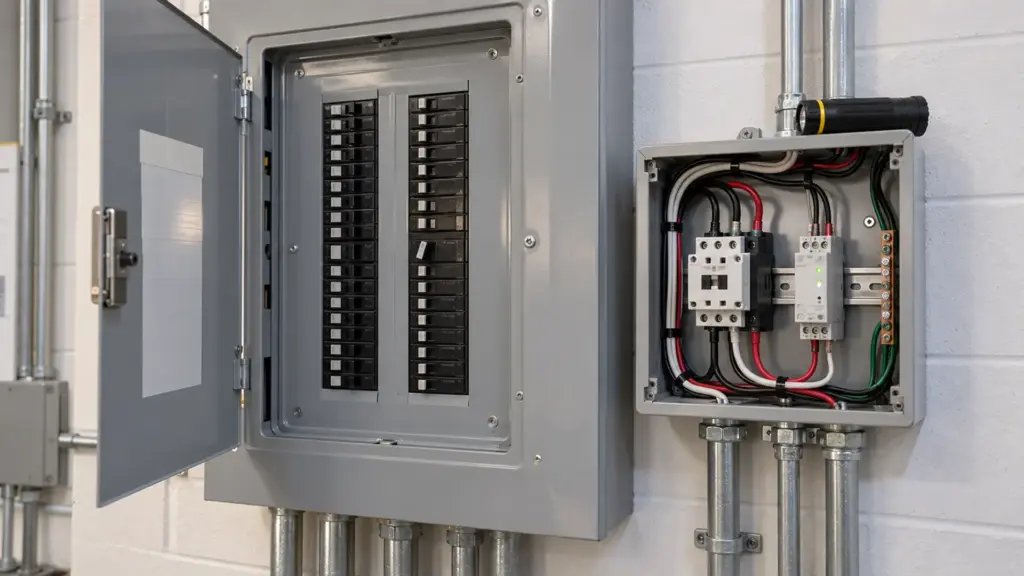
Do not put in a larger breaker. The breaker protects the conductors, and its rating is set by the wire, not by the lighting. A 30 A breaker on 20 A wire is a code problem that happens to stop the nuisance trip.
Do not assume a different breaker type is a free fix either. Some breaker families are made for lighting loads with high inrush, and they can help, but whether they suit a given driver load is a question for the breaker maker’s curves, not a guess.
And if the device that trips is a GFCI or an AFCI rather than a standard breaker, the cause may be leakage current or the device reading the switch-on as an arc. That is a different fault with different fixes, and our LED strip troubleshooting order starts from the device that tripped.
For drivers, ask for the inrush figure with the datasheet when you quote. Our Class 2 and linear drivers take 100 to 277 V input, and we send the inrush data for the exact model so the circuit count is set before the panel schedule is final. If a driver is already installed and tripping, the readings in LED driver troubleshooting separate an inrush trip from a driver fault.
Rules of Thumb
- A trip at switch-on with a light steady load is inrush until proven otherwise.
- Count drivers per breaker twice: once by watts, once by inrush. Use the lower number.
- Read inrush at the circuit’s real voltage. 277 V is worse than 120 V.
- More small drivers means more inrush events; that is the cost of short Class 2 runs.
- Fix it in this order: split, stagger, limit, switch at zero, then change the driver.
- Never fix it by upsizing the breaker past the wire.
- Plan the circuit count before the quote. It is one line in a quote that keeps its margin.