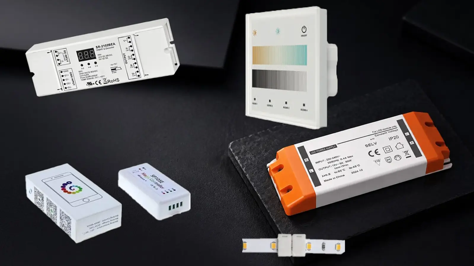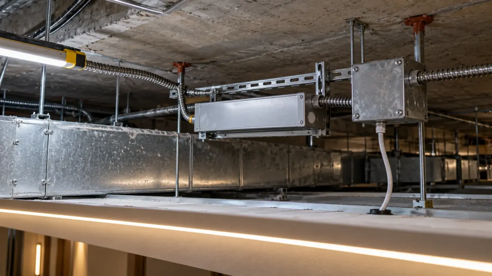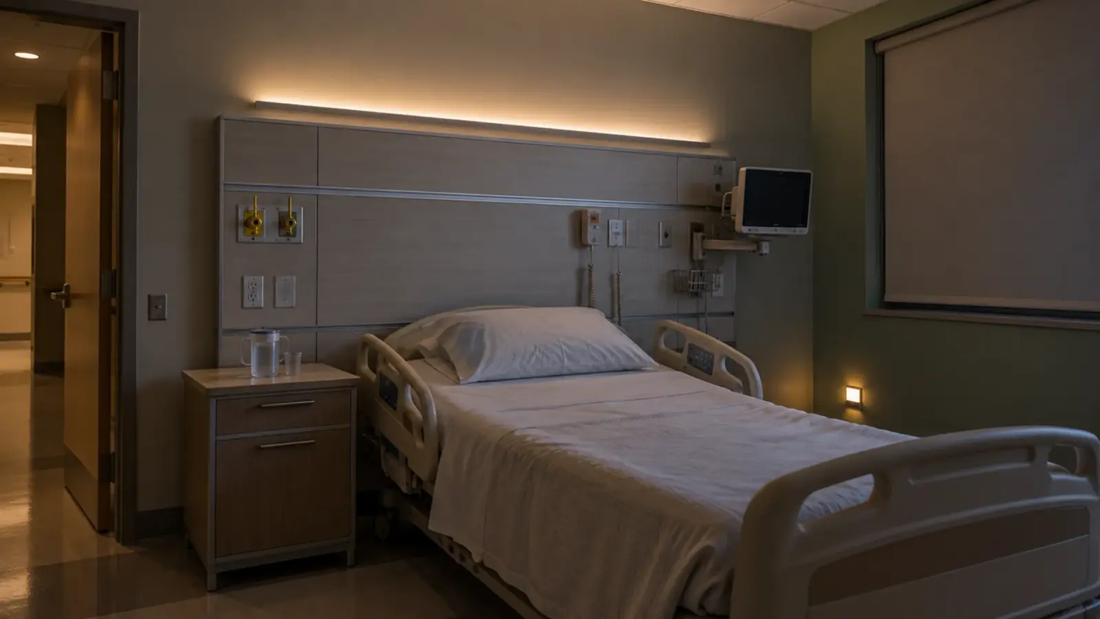
Dim it, through a driver that can go to off and stays powered; switch it only where the code wants the room dark and the relay is rated for the drivers it carries. That is the occupancy sensor and LED strip driver wiring decision in one sentence.
The rest of this page is the four gates that get a job to it: what the energy code asks of the space, whether the driver can dim to off, how many drivers a relay can wake up, and what the room sees when the lights come back.
Two Paths From Sensor to Strip
An occupancy sensor can reach an LED strip two ways. On the first path the sensor’s relay, or a power pack it controls, opens the line conductor to the driver. The driver loses power, the strip goes dark, and when the sensor sees motion the relay closes and the driver starts from cold. On the second path the driver stays powered and the sensor sends a 0-10V signal that dims the strip to a low level, or to off, and raises it again.
A Lutron patent on load control devices states the difference plainly. If the switched hot goes to zero, “the 0-10V driver will then be unpowered and unable to respond to the occupancy sensors, vacancy sensors, and/or daylight sensors”; the alternative is a standby state in which the driver “remains powered, but turns off the LED light source”. The first path is a switch; the second is a control. The code decides which the space needs, the driver decides whether the second is available, and the relay decides whether the first is safe.
Gate 1: What the Code Asks of the Space
The adopted energy code names the sequence, and the sequence names the path. California’s 2025 Title 24, Section 130.1(c), is the strictest common case; ASHRAE 90.1-2022 and the IECC are the others, and the local amendment governs.
| Space | Title 24 2025, 130.1(c) | ASHRAE 90.1-2022, as summarized by Lutron | Path that satisfies it |
|---|---|---|---|
| Restroom, office ≤250 sq ft, classroom, conference room, multipurpose <1,000 sq ft | Occupant sensor shall “automatically shut OFF all of the lighting in 20 minutes or less after the control zone is unoccupied”; partial-ON (50–70 percent) or vacancy manual-ON where multilevel control is required | Off, or reduced by at least 50 percent, within 20 minutes vacant (15 minutes under Addendum bd); auto-on limited to 50 percent in most spaces | Switch, or dim-to-off; partial-ON needs the dimming path |
| Corridor, stairwell | Controls shall “separately reduce the lighting power in each space by at least 50 percent when the space is unoccupied” | Corridors may be automatic full-on; 20-minute reduction or off | Dimming path (partial-off), with the driver powered |
| Office >250 sq ft | Zones ≤600 sq ft; reduced to 20 percent or less, then all off, within 20 minutes of vacancy | Zones ≤600 sq ft; 80 percent reduction or off within 20 minutes of zone vacancy (open offices over 300 sq ft); auto-on ≤50 percent | Dimming path with a timed off, or dim then switch |
Two readings follow. Anything the code wants partially on or off, a corridor at 50 percent, a classroom that comes on at 50 to 70 percent, an office stepping to 20 percent, is a dimming sequence and the driver has to stay powered for it. Anything the code wants dark, a restroom after 20 minutes, can be a switch. Our Title 24 guide covers the California text in detail; the Lutron summary is one vendor’s reading of 90.1-2022 as first published, and Addendum bd, approved in 2025, shortens the occupancy delay from 20 to 15 minutes.
Gate 2: Can the Driver Dim to Off and Stay Powered?
The dimming path has a condition the patent names: “Some 0-10 V drivers may be responsive to occupancy sensors, vacancy sensors, and/or daylight sensors.” Some. A 0-10V driver dims to its minimum on a low signal; whether it goes to no light output at 0 V, holds that state without flicker, and wakes cleanly on the next signal is a datasheet property called dim-to-off or standby. A driver without it leaves the strip glowing at its minimum in an empty corridor all night, which is the fault our faint glow guide describes.
White COB strip dims below 1 percent with a compatible 0-10V driver, and our 0-10V Class 2 driver is UT-D60-24-C2-010; whether it holds a true off and a standby on the line is confirmed on its datasheet at quote, and the same question goes to every driver on the submittal. The market splits into two classes. Mean Well’s HLG-60H B-type takes a 1 to 10 V signal and its published curve bottoms at 10 percent; it does not switch its output off, so a true off needs the relay. Its XLG AB-type takes 0 to 10 V and lists a standby of under 0.5 W with dimming off, and Euchips’ EUP75A-1H24V-1 is rated “0.1%-100% Dimming to off” with full output when no dimming signal is connected. Ask which class a driver belongs to, in those words, before the sequence is drawn. Where the control system has a 0-10V channel but the drivers are non-dimming, a 0-10V decoder such as UT-C010-350 on the 24V side gives the dimming path without changing the drivers, at 350 W per channel. Our dimming protocols guide sets out how each control reaches a driver, and the rule from our drivers page holds: a 0-10V driver needs a 0-10V control, and mixing them is the most common cause of flicker.
One wiring detail that fails inspection: the sensor’s 0-10V output is a low-voltage control circuit, and the patent notes that “Prior art 0-10V drivers typically source between 1-2 milliamperes of current” on that pair. Ten drivers on one sensor output is 10 to 20 mA of sink; check the sensor’s rated number of drivers, and keep the 0-10V pair (usually violet and gray) separate from power conductors as the control maker’s instructions require.
Gate 3: How Many Drivers on One Relay
The switching path has a different limit, and it is the one that comes back as a callback. An LED driver is a capacitive load; at the instant the relay closes, the driver’s input capacitors charge through the contacts in a surge far above the running current. A family of Lutron patents on stuck-relay detection gives the scale: for a full 16 A steady-state circuit of drivers the inrush can approach 560 A, a surge that “can wreak havoc on the contacts of even a relatively large relay having a high current rating (e.g., 50 amps)”, and the failure is “more commonly due to welding of the contacts in the closed position”. A Mike Holt forum poster, on a circuit of electronic ballasts (the same mechanism), reported three ceiling sensors that failed stuck on, and the reply was the same: “the inrush welds the contacts together after some time”.
| Circuit | Steady current at 120 V | What the relay sees at close | Rating to use |
|---|---|---|---|
| One UT-D60-24-C2 driver at 60 W | 0.5 A | A brief surge many times 0.5 A | The sensor’s LED rating in watts or number of drivers |
| Eight drivers, a 60 ft corridor cove at 2.4 W/ft in 16 ft feeds plus spares | 4 A | Eight surges at once | The maker’s LED rating, not the general-purpose amps |
| Sixteen drivers on one power pack | 8 A | Half the patent’s 16 A example | A power pack rated for LED drivers, or split the load |
The arithmetic that matters is not the steady current; it is the number of drivers that charge at once. Sensor and power-pack makers rate their relays for LED loads separately from incandescent or ballast loads, sometimes as a count of drivers; use that rating, not the general-purpose incandescent or ballast wattage on the box. A driver’s own inrush also trips breakers on large circuits, as our inrush guide explains; the relay sees the same event at every cycle. The strip itself does not mind: our CSP construction is type-tested through 15,000 on/off cycles, and the strip is not the wearing part. The relay is the part that wears.
The mitigation is to put fewer drivers behind each relay, to use one larger linear driver (UT-D150-24-L or UT-D400-24-L) in place of several small ones where the wiring method allows, or to take the dimming path and let the driver stay powered, so the relay never sees the surge.
Gate 4: The Restart the Room Will See
A switched driver starts from cold, and a cold start typically has a delay, from a fraction of a second to a second or more depending on the driver, before the strip lights. In a restroom that is fine. In a corridor it is the dark second a person walks into, and if the sensor’s coverage starts at the door the person is three steps in before the light comes. On the dimming path the strip is already powered and at its low level, and the rise to full is immediate and smooth.
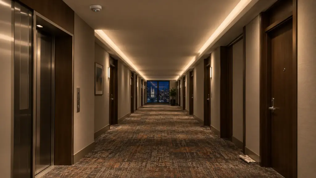
Fade matters as well. A relay drops the strip to black; a dimming sequence can fade down over seconds so the corridor empties into a dim line rather than a dark one. Where a sensor-dimmer product does both, its off-warning fade is a feature worth specifying. Decide the restart you want before the sensor is chosen, and test it on the first zone with the real driver; our dimmer and driver test is the bench procedure.
The Sequence for a Corridor at 50 Percent
A corridor is the clearest case for the dimming path, because the code asks for exactly what a relay cannot do.
- 1Vacantall zonesAt or below 50% (Title 24 130.1(c)6C)
- 2Motion, zone 1sensor 1Zone 1 to full
- 3Reaches zone 2sensor 2Zone 2 to full; zone 1 starts its 20-minute timer
- 420 minutes vacanttimerBack to 50%; scheduled off by relay at night
A typical job: a 120 ft (36.6 m) hospital corridor with a cove on both walls, UT-C320-8 COB at 2.4 W/ft, split into three zones of 40 ft per wall. Each zone has its own 0-10V driver set (or a 0-10V decoder) and a ceiling sensor covering its length. Occupied: the sensor’s signal holds the drivers at the design level. Twenty minutes vacant: the signal drops to the level the designer set at or below 50 percent of power, per Title 24 130.1(c)6C, and each zone does it “separately”. Motion at one end: that zone rises to full and the next zone follows as the person reaches its sensor. The drivers never lose power, so there is no cold start, no relay surge and no dark second. A time-of-day input from the building control can take the night level lower still, within the code’s floor.

The one thing the dimming path cannot do is turn the circuit off, so where the code or the owner wants a true off, a relay in series with the dimming path does it at the scheduled time, with the drivers already at their low level when the contacts open; a relay that opens on a dimmed load sees a smaller surge at the next close than one that cuts a full-output circuit.
Restrooms, Small Offices and Classrooms
These are the switch-or-dim-to-off spaces. Title 24 wants them dark within 20 minutes of vacancy, and a restroom’s two zones, a mirror strip and a cove, both go. The switching path works here: one sensor relay rated for the two or three drivers in the room, a cold start the user does not mind, and the strip dark on schedule. The dimming path works too, if the drivers dim to off, and it is the only path when the room is a classroom or a conference room under multilevel control, where the code asks the lights to come on at 50 to 70 percent or by a manual switch only. Our schools guide places the sensor and the whiteboard zone; in a clinic exam room the task strip over the counter is usually a vacancy-type circuit the clinician turns on by hand and the sensor turns off.

120V Strip: The Case With No Driver
Direct-AC strip such as UT-H120-120 has no driver to dim and no 0-10V input. A sensor controls it the only way it can, on the line side, wired with line-voltage methods and confirmed with the AHJ, and the switched load is the strip’s own electronics along its length. It is the right fit for a stock room, a storage corridor or a parking level perimeter where the code accepts full-off and nobody minds the restart; it is the wrong fit for a corridor that has to hold 50 percent. Our 120V vs 24V guide carries the decision.
Mistakes That Come Back as Callbacks
- A general-purpose sensor relay carrying a corridor’s worth of drivers, failing stuck on after a year.
- A non-dim driver on a 0-10V sensor, so the corridor cannot hold 50 percent and the inspector writes it up.
- A dimming driver without dim-to-off on a restroom, glowing at minimum all night.
- A sensor without a neutral where the sensor needs one; many line-voltage 0-10V sensors, such as Leviton’s OSM3D-DDW, are 120–277 VAC and need a neutral.
- A sensor’s coverage starting at the door, so a switched corridor is entered dark.
- No bench test of sensor, driver and strip together before the floor is wired; our install checklist and handover guide put it on the list.
FAQ
Can an occupancy sensor control LED strip lights?
Yes, two ways: a relay that cuts the line to the driver, or a 0-10V signal that dims a powered driver to a low level or off. The energy code’s sequence for the space decides which; corridors that must hold 50 percent need the dimming path.
Do LED drivers dim to off with 0-10V?
Some do. Dim-to-off and standby are datasheet properties; a driver without them sits at its minimum output on a 0 V signal. Confirm it for every driver on the submittal, including ours, and test it on the first zone.
Why does an occupancy sensor stay on with LED lights?
Usually a welded relay. LED drivers draw a large inrush at the instant the relay closes, and repeated surges weld the contacts shut. Use the sensor maker’s LED load rating, put fewer drivers on each relay, or take the dimming path so the driver stays powered.
How many LED drivers can an occupancy sensor switch?
As many as the sensor or power pack is rated for with LED drivers, which is usually far fewer than its general-purpose wattage implies. The limit is the inrush of all the drivers charging at once, not their running watts.
Decision Rule
Read the space’s code sequence first. If it asks for partial-on, partial-off or a 50 percent hold, the sensor dims a powered driver, and the driver has to dim to off if the sequence ends dark. If it asks only for off within 20 minutes, a relay rated for the drivers it carries is acceptable, with the restart the room will tolerate. Never put a general-purpose relay on a corridor’s worth of drivers, and never leave a dimming driver without dim-to-off on a room that has to go dark.
Unitop Lighting supplies 0-10V dimmable Class 2 drivers, 0-10V decoders and linear drivers matched to our dot-free COB LED strip for office, school and healthcare projects across the US; the sensor and driver pairing, the drivers per zone and the dim-to-off behavior are confirmed at quote. Send the control sequence and the corridor plan and request a quote.