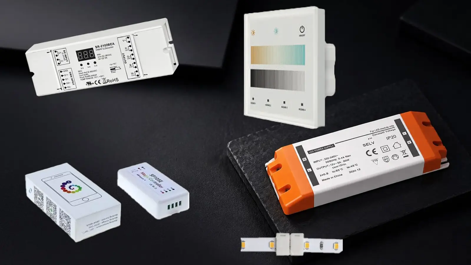
Two wires, three, five or six: the count at the end of the strip tells you which diagram you need, and the label printed on each pad tells you where each wire lands. Every diagram below is the same chain, supply to controller to strip, with one more channel each time the wire count goes up.
The diagrams use our 24V range as the example. Terminal names differ between makers, so treat the drawings as the pattern and the pad labels and the controller’s terminal names as the instruction. Wire colors are not standardized at all; never wire by color alone.
Before Any Diagram: Count the Wires
| Strip circuit | Conductors at the strip | What controls it |
|---|---|---|
| Single color | 2: V+ and V− | A dimmable driver, or a fixed driver plus a dimming decoder |
| Tunable white (3-wire) | 3: shared V+, warm, cool | A two-channel tunable white controller |
| RGB | 4: shared V+, R, G, B | A three- or four-channel controller |
| RGBW | 5: shared V+, R, G, B, W | A four-channel controller |
| RGB + tunable white | 6: shared V+, R, G, B, warm, cool | A five-channel controller |
Checkpoint: count the pads on a cut end of the actual strip before you order the controller. A 5-pin strip can be RGBW or RGB plus one white, depending on the maker, and the pad labels settle it.
Single Color: Two Wires
The simplest diagram has three parts: a constant-voltage supply, a way to dim it, and the strip.
- Dimmable driver: line voltage and the control signal go to the driver; two wires go from the driver’s output to the strip. Our UT-D60-24-C2-010 takes 0-10V; UT-D60-24-TRC takes forward or reverse phase (TRIAC) dimming.
- Fixed driver plus decoder: a non-dimming 24V supply feeds a decoder, and the decoder’s output feeds the strip. The UT-C010-350 decoder takes 12–24V DC and a 0-10V signal and handles up to 350 W on one channel.
Polarity matters. Supply V+ goes to the strip pad marked + (or V+), V− to −. A strip wired backwards stays dark. Find the fault with a meter at the pads before the strip is fixed in place, not after.
Checkpoint: before mounting, power the strip on the bench at full and at minimum dim, and confirm the far end of each run is as bright as the near end.
Several Runs on One Driver
When one driver feeds several runs, each run gets its own pair of wires back to the driver’s output or to a distribution block beside it. Do not jump from the end of one run to the start of the next: the second run then shares the first run’s copper, and its far end is dimmer than any run on its own feed. Keep the total load on the driver inside its rating, with the loading margin our power supply sizing guide uses.
- 1Line voltage120–277 VACTo the driver input
- 2Driver or supply24V constant voltageDimmable (0-10V, TRIAC) or fixed
- 3DecoderOnly with a fixed supply0-10V in, 24V out
- 4V+ and V−2 conductorsPolarity from the pad label
- 5Strip+ and − padsTest full and minimum dim
Tunable White: Three Wires, One Shared Positive
A 3-wire tunable white strip carries two rows of LEDs, one warm and one cool, on one common positive. The controller switches the negative side of each row to mix the two.
Wiring, in order:
- Supply V+ and V− to the controller input.
- Controller common positive (V+) to the strip’s shared + pad.
- Controller warm-white output to the warm pad (often marked WW).
- Controller cool-white output to the cool pad (often marked CW).
Swap steps 3 and 4 and the run turns warm when the wall control says cool. On a DALI system, UT-CDALI-DT8 is a two-channel DT8 controller with 12–24V input and 360 W total; on 0-10V or RF systems the controller changes, but the three-wire pattern stays.
Some tunable strips use two wires instead of three. UT-T576-8, a 2-wire dim and CCT COB, changes color temperature through the controller rather than through a third conductor, and it needs the controller made for it. Confirm the controller at quote for any 2-wire tunable strip.
Checkpoint: set the controller to full warm and walk the run; every section must be warm. Then full cool.
- 124V supplyConstant voltageTo the controller input
- 2ControllerTwo channelsDALI DT8, 0-10V or RF
- 3Shared +Common positiveTo the strip + pad
- 4WWSwitched negativeWarm white pad
- 5CWSwitched negativeCool white pad
RGBW: Five Wires, Four Channels
RGBW adds a white channel to red, green and blue, so the strip has five pads: one shared positive and four channel negatives. RGB is the same diagram without W; RGB plus tunable white adds a sixth wire for the second white.
- Supply to the controller input.
- Controller V+ (common) to the strip’s + pad.
- R, G, B and W outputs to the matching pads.
A DMX system uses a decoder per run or zone: UT-CDMX-480 is a four-channel DMX512 decoder rated 480 W in total. An RF system uses a receiver such as UT-CRF-24G, with four zones and 360 W in total. Our RGB vs RGBW guide covers which white to choose; the wiring is the same either way.
Checkpoint: drive each channel alone at full. Red must be red on every section; if one section shows green, its R and G wires are crossed at that joint.
- 124V supplyConstant voltageTo the controller input
- 2ControllerFour channelsDMX decoder or RF receiver
- 3Common +Shared positiveTo the strip + pad
- 4R, G, B, WFour negativesMatch each pad label
- 5AmplifierOwn 24V supplySame channel order out
RGB Plus Tunable White: Six Wires
RGB plus tunable white, sometimes written RGBCCT, puts a full color row and a two-white row on one strip. The strip has six pads: the shared positive, R, G, B, warm and cool. Our UT-RCCT72-12 and UT-RCCT90-12 are built this way, with 5050 RGB packages and 2835 tunable white packages on one board.
The diagram is the RGBW diagram with one more output: a five-channel controller, or a four-channel unit plus a second controller for the whites if the control system splits color and white. Two things to settle before rough-in:
- The cable. Six conductors from the controller to every run, which rules out most standard four- and five-conductor cable. Order the cable with the strip.
- The connector. Our connector table lists single color, CCT, RGB and RGBW circuits; a six-conductor joint for RGB plus tunable white is confirmed at quote, or the joint is soldered.
Checkpoint: run each of the five channels alone, then both whites together at full, before the cove lip goes on.
Where the Controller Goes
The controller is the part most often buried. Place it where three conditions hold:
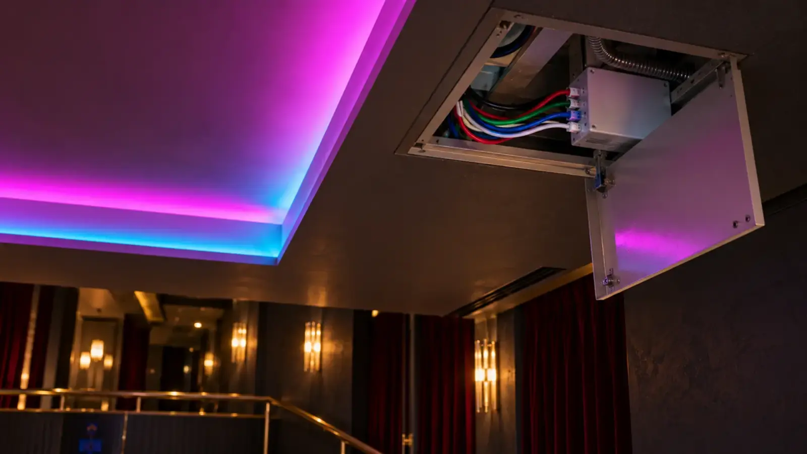
- Reachable without demolition: an access panel, a millwork cabinet or the driver closet, not above a hard ceiling with no hatch.
- Close to the runs it feeds: each output line from the controller to the strip carries that channel’s full current, so it loses voltage like any feed. A long run of thin multi-conductor cable between the controller and the strip dims the far end of every channel at once.
- Ventilated and inside its rating: decoders and receivers are small and run warm at full load; do not pack them against insulation.
If the control signal has to travel a long way, move the controller close to the strip and run the signal (DMX, DALI, 0-10V) the long distance instead of the power channels. Signal cable carries almost no current; channel conductors carry all of it.
Current per Channel: Size the Controller
A controller has two limits: the total load and the load per channel. Our table lists total ratings; the per-channel rating is on the controller’s datasheet, and it is the one most often exceeded, because a single color or a single white can run at full while the others are off.
Work out both for each run. Current equals the watts on that channel divided by the voltage.
| Run at 24V | Strip power | Total current | Per channel |
|---|---|---|---|
| 16 ft UT-C480-8 single color | 3.2 W/ft, 51 W | 2.1 A | 2.1 A (one channel) |
| 16 ft UT-T168-10 tunable white | 4.3 W/ft (2.1 + 2.1), 69 W | 2.9 A | about 1.4 A warm, 1.4 A cool |
| 16 ft UT-RW84-12 RGBW | 5.8 W/ft, 93 W | 3.9 A | from the datasheet split; W is often the largest |
Totals are our arithmetic from the spec tables (W/ft × length ÷ 24V). For RGBW, our page publishes the total only; size each controller channel for the largest single channel on the model’s datasheet, not for the total divided by four.
Then add the runs on one controller and compare with its total rating. Four 16 ft RGBW runs at about 93 W each come to about 372 W: inside UT-CDMX-480’s 480 W, over UT-CRF-24G’s 360 W.
Long Runs: Feeds and Amplifiers
The rules for feeds do not change with the number of channels. Each run gets power within its rated length per feed, 16 ft (5 m) for most of the strips above, and parallel feeds, never one run daisy-chained from the end of another. Our voltage drop guide explains why.
When one controller cannot carry all the runs, a signal amplifier repeats its outputs. UT-CAMP-4 takes the controller’s four PWM channels in, repeats them to the next group of runs, and carries up to 384 W from its own supply. Keep the channel order identical through the amplifier: R to R, G to G, B to B, W to W. A swap at the amplifier shows as one whole zone in the wrong color.
Multi-conductor cable between the controller and the strip is a wiring question of its own; our in-wall wiring guide covers the cable marking.
Labels at Both Ends
A wiring diagram on the drawing is only half the record. The other half is at the wires.
- Give each run a number on the drawing and on the driver schedule.
- Label every conductor at the controller and at the strip with the run number and channel, for example “R12-W” for run 12, white.
- Write the channel order inside the controller cover.
- Use one convention for the whole job, and give it to whoever services the system.
- Photograph each open joint before the cover goes on, and file the photos with the as-built drawings.
A labeled RGBW joint takes minutes to check; an unlabeled one inside a closed cove takes a ladder, a meter and guesswork. Our connector guide covers which joint suits each location.
Symptoms and Fixes
Most wiring faults show on the first full test, which is why each section above ends with a checkpoint. When one slips through, the symptom usually points to the wire.
| Symptom | Likely cause | Fix |
|---|---|---|
| Whole run dark | Polarity reversed, or common V+ not connected | Check + at the strip pad with a meter |
| Warm comes on when set to cool | WW and CW swapped | Swap the two white wires at the controller |
| One section the wrong color | R/G/B crossed at that joint or connector | Re-terminate the joint by pad label |
| Whole zone the wrong color | Channel order changed at an amplifier | Match amplifier in/out channel order |
| One color missing on a run | Open channel wire or loose clip | Re-seat or re-solder that conductor |
| Far end dimmer | Run past its per-feed length | Add a parallel feed |
| Flicker when dimmed | Driver and controller not a matched pair | Check the dimming method on both |
| Controller hot or shuts off | One channel over its rating | Split runs or add an amplifier |
The controllers, decoders and amplifiers named here are listed with their ratings on our drivers, controllers and connectors page.