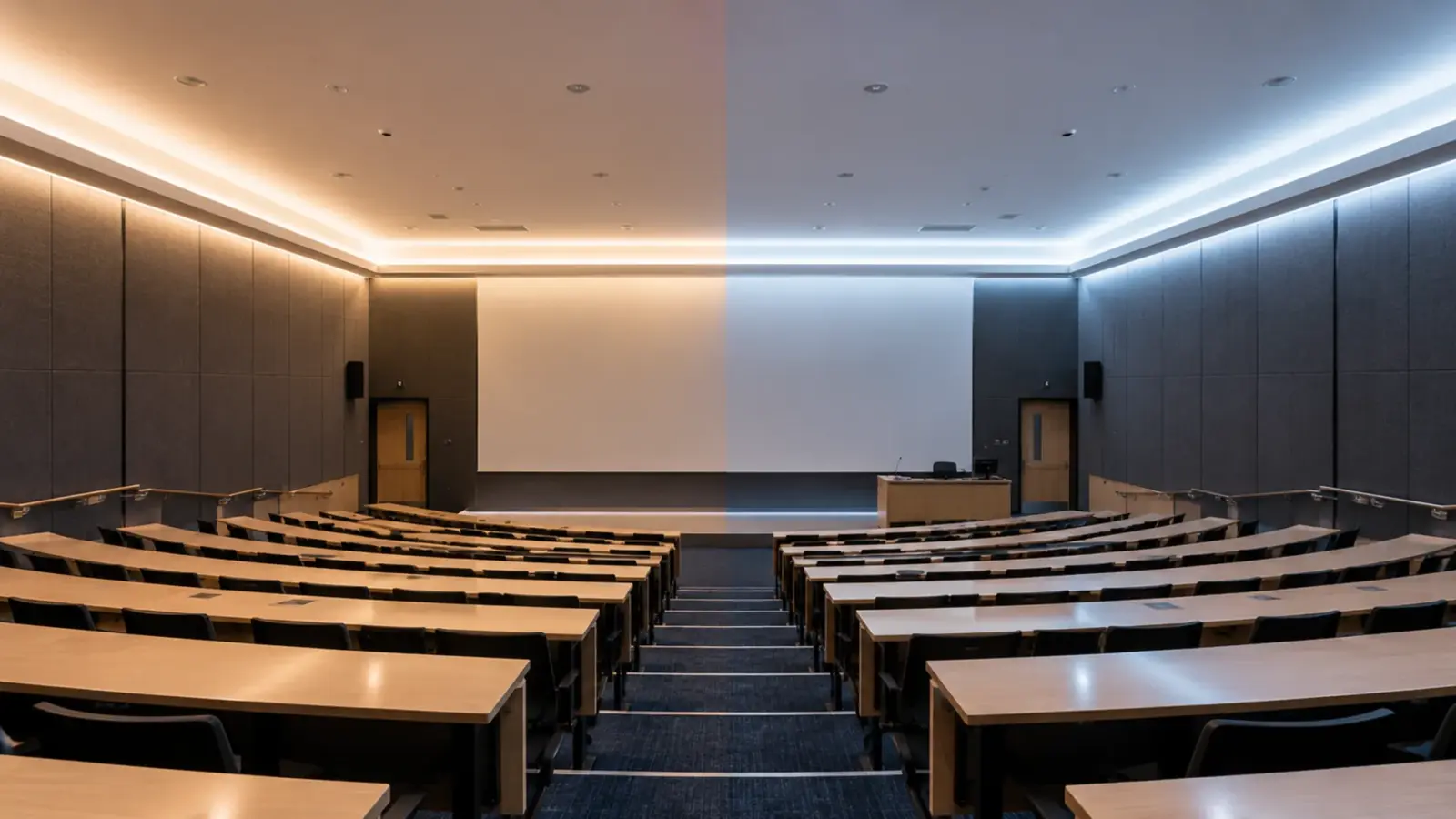
A DT8 decoder takes one DALI address for both light level and colour temperature, and the strip itself knows nothing about DALI. Planning DALI DT8 tunable white LED strip therefore comes down to three choices made before rough-in, the decoder, its supply and the address count, plus one setting made at commissioning:
- The strip has two channels; the DT8 part is the decoder between a constant-voltage supply and the strip.
- The supply choice sets how many decoders, and so how many addresses, a room uses.
- The DALI pair is not low-voltage wiring in the Class 2 sense.
- Rooms match only when every decoder has the same Tc limits.
What DT8 Changes on a Strip Job
DALI Device Type 8 is the colour-control part of the standard, IEC 62386-209, and Tc is its colour-temperature mode, the one the industry calls tunable white. The DALI Alliance added Tc tests to DALI-2 certification in February 2020. On the device side the point is the address count: Lunatone’s DT8 converter datasheet lists “1 DALI Address (DT8, Type Tc)” for two output channels, and Sunricher’s DT8 dimmer manual says “Each device is controlled via a single DALI address.” Colour temperature travels on the bus in mirek, one million divided by the kelvin value, so 2700K is 370 mirek and 6500K is about 154.
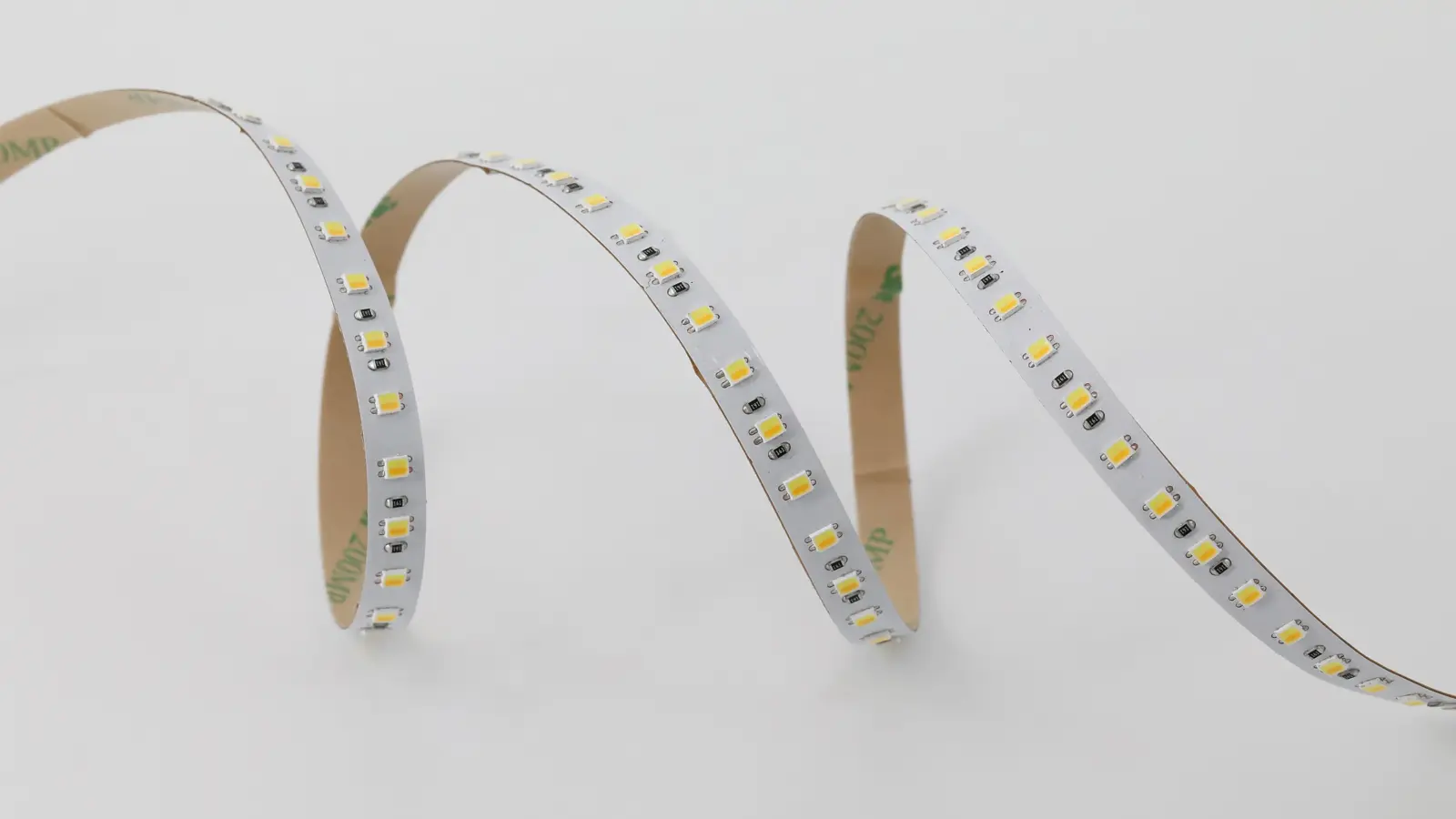
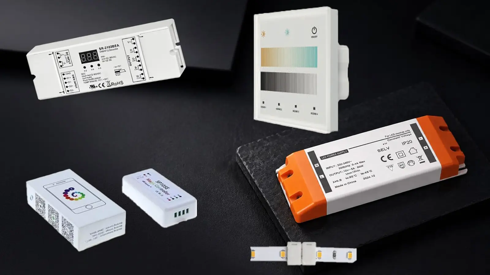
On a strip job that address lives in a decoder, not in the strip. A tunable strip such as UT-T624-8 is a 3-wire COB strip: a common positive and one negative each for the warm and cool LEDs, which our wiring diagram guide draws out. Our UT-CDALI-DT8 is the two-channel DT8 controller that sits between a 24V supply and that strip: 12–24V DC in, 360 W total, two CCT channels, DALI bus in.
The alternative is Device Type 6, which only dims. A DT6 setup for tunable white puts each channel on its own address and leaves the colour mix to the front end. DT8 sends level and colour temperature as separate commands to one address, so a “4000K at 60%” scene is one scene entry per decoder.
Checkpoint: confirm the front end speaks Part 209 Tc. A controller that only sends DT6 commands will dim a DT8 decoder but never change its colour. Sunricher’s DT8 dimmer manual states the same condition from the other side: it is “Compatible with universal DALI masters that supports DT8 commands.” Our dimming guide covers how to choose between DALI and the other protocols; this guide assumes DALI is chosen.
Pick the Decoder and Its Supply
The decoder is constant-voltage. It takes the 24V output of an ordinary constant-voltage supply and switches it to the two channels, so the strip, the decoder and the supply all have to share one voltage, 24V for the strips in the table below; the decoder accepts 12–24V. A constant-current DT8 driver, the kind sold for LED modules, is the wrong part for strip, a mistake that turns up in installer forums.
Size the decoder for both channels at full: unless the datasheet gives a lower combined limit, plan for the warm and cool LEDs both at 100%. Applying the same 80% load rule we use for drivers, 360 W gives 288 W of strip per decoder:
| Strip (24V) | Both channels | Strip per UT-CDALI-DT8 (288 W) | Strip per 60 W Class 2 supply (48 W) |
|---|---|---|---|
| UT-T120-8, 2835 WW+W | 2.9 W/ft | 99 ft | 16 ft |
| UT-T624-8, COB 3-wire | 4.3 W/ft | 66 ft | 11 ft |
| UT-T640-10, COB | 4.9 W/ft | 58 ft | 9 ft |
| UT-T640-10-CSP | 4.9 W/ft | 58 ft | 9 ft |
| UT-T240-10, 2835 | 5.8 W/ft | 49 ft | 8 ft |
Every one of those strips is rated 16 ft (5 m) per feed, so 66 ft of UT-T624-8 on one decoder still means five feeds wired back to the decoder’s outputs, never one 66 ft chain. Our power supply sizing guide covers the supply side of the same arithmetic.
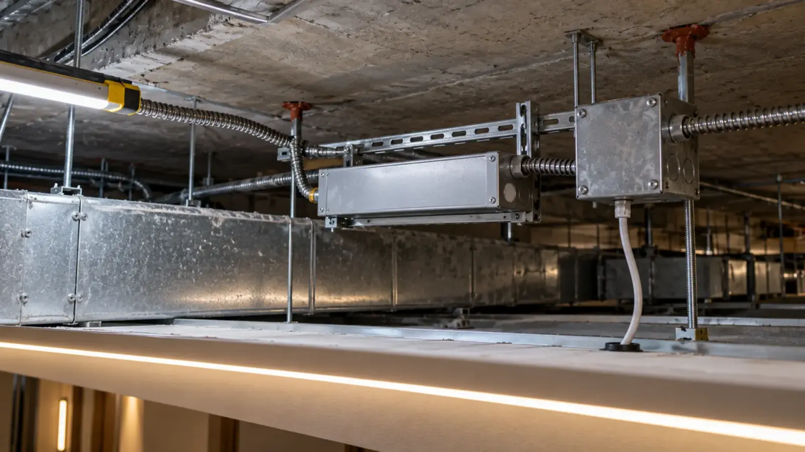
Where the decoder sits matters as much as its rating. It carries the full strip current on two channels plus the common, so the leads from decoder to strip are sized like any 24V feed and kept short; a decoder in the corridor ceiling feeding a classroom cove 40 ft away loses voltage on the warm and cool legs alike. Put each decoder above an accessible ceiling within a few feet of the zone it serves, beside its supply, and treat both as equipment someone will have to replace.
Count the Addresses Before You Pick the Supply
The last column of that table is where DT8 jobs get decided. A DALI line carries 64 devices, Tridonic’s quick guide confirms, and every decoder is one of them. Take a typical job: a 30 by 24 ft classroom with a perimeter cove of UT-T624-8, 108 ft at 4.3 W/ft, 464 W with both channels at full.
| Layout per classroom | Supplies | Decoders (addresses) | 30 classrooms, DT8 | 30 classrooms, two-channel DT6 |
|---|---|---|---|---|
| 60 W Class 2 supplies, one decoder each, 11 ft runs | 10 × UT-D60-24-C2 | 10 | 300 addresses, 5 DALI lines | 600 addresses, 10 lines |
| 400 W supplies, decoders at 232 W each | 2 × UT-D400-24-L | 2 | 60 addresses, 1 line (4 spare) | 120 addresses, 2 lines |
The Class 2 layout keeps every supply output inside the Class 2 limits our Class 2 driver guide explains, at the cost of ten decoders, ten addresses and ten supplies per room, and five bus supplies for the school. Whether a decoder’s output still counts as Class 2 when its input does is a question for the AHJ, not one the decoder’s label settles. The 400 W layout needs two decoders per room and fits the whole school on one line, but the strip wiring downstream is not Class 2 and is run as such; on paper it is one line, and in practice the 300 m rule below may split it by wing. Most school and office jobs land in between: one decoder per zone the room is actually controlled as, sized to the zone.
Each line also needs its own DALI bus power supply, Tridonic’s guide notes, and that supply’s current, 250 mA at most, is shared by every device on the line. Plan lines by floor or wing, keep the count below 64 so a zone added in a later renovation has an address to go to, and show each bus supply on the drawings with the decoders it serves.
Checkpoint: write the address count on the drawings before the supplies are bought. Changing from the Class 2 layout to the 400 W layout after rough-in moves boxes and changes the wiring method.
Wire the Bus: Non-SELV Next to Class 2
The DALI pair looks like low-voltage control wire and is not treated that way. Tridonic’s guide lists the DALI voltage as 12.0 to 20.5 V, “typically 16 V DC”, and marks it “Non SELV, because no galvanic isolation”; the system is installed “with customary installation material for mains voltage”, and “mains voltage and bus line can be led in the same cable”. Lunatone’s DT8 converter datasheet says the same in its insulation data: “DALI / mains not isolated”.
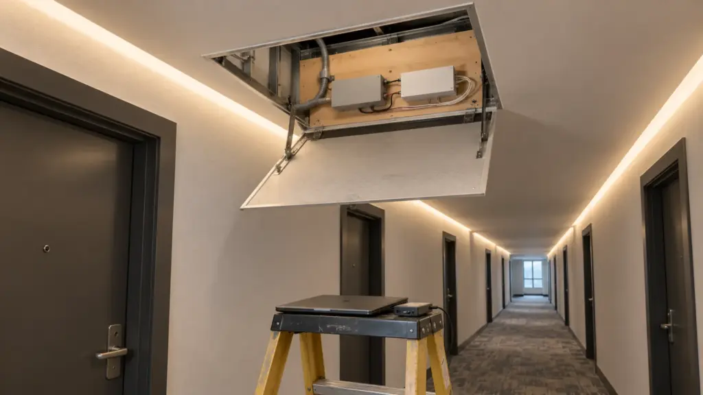
At a strip decoder that matters because the 24V leads beside it are Class 2. Lutron’s LED driver installation guide calls for Class 2 wiring to be kept 0.25 in (6 mm) from Class 1 and line-voltage wiring or behind a barrier. Run the DALI pair with line-voltage methods, land it on the decoder’s bus terminals, and keep it apart from the strip leads inside the box.
The bus has a length limit set by voltage drop: no more than 2 V at the 250 mA maximum, one bus supply per line. Tridonic’s formula reduces to length in meters = 4 × 56 × cross-section in mm², with the 300 m figure as the ceiling, and the DALI Alliance’s tech note measures it between any two devices.
| DALI pair | Cross-section | Formula length | Use |
|---|---|---|---|
| 18 AWG | 0.82 mm² | 184 m (604 ft) | Short lines only |
| 16 AWG | 1.31 mm² | 293 m (961 ft) | Most floors |
| 14 AWG | 2.08 mm² | 466 m, capped at 300 m (984 ft) | Long lines |
Set the Colour Type and Tc Limits
Tc limits are where two rooms stop matching. A DT8 decoder carries two sets of numbers, and Sunricher’s DT8 manual shows both: physical lower and upper limits, which describe the LEDs connected, and an operating range, warmest and coolest, which “is restricted to the physical upper and lower limits”. Its factory defaults read 2702 K and 6493 K. Those odd numbers are 370 and 154 mirek converted back to kelvin, the 2700K and 6500K ends of a common tunable strip.
The five strips in the table are 2700–6500K, so set the physical limits to those ends; the decoder then maps a 4000K command onto the strip’s real mix. Narrow the operating range where the design wants it, for example 3000–5000K in classrooms, so a wall control cannot push a room to an end the designer rejected. The IEC 62386-209 implementation documented by Beckhoff makes no change when a step command reaches the coolest or warmest value, and flags “Colour temperature Tc out of range” when the decoder cannot reach a requested value.
Checkpoint: set the colour type to Tc before anything else. Sunricher’s manual asks for this before commissioning, and Beckhoff’s documentation shows Tc commands executed only when the colour type Tc is active. Then read the limits back from every decoder. Our colour mismatch guide lists different Tc limits per decoder as a cause of two runs that do not match.
Groups, Scenes and the Levels After a Power Cut
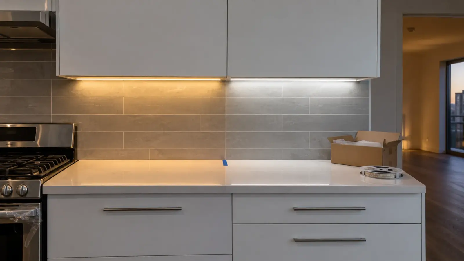
Each DT8 decoder joins up to 16 groups and stores up to 16 scenes, and a DT8 scene holds both a level and a colour temperature. Put each room in its own group and each zone in a second one, then build scenes for what the room does, not what the strip can do. A classroom set, as an example of what a designer might ask for:
| Scene | Level | Colour temperature | Use |
|---|---|---|---|
| General | 80% | 4000K | Teaching |
| Projection | 30% | 3000K | Screen in use, front zone lower |
| Testing | 100% | 5000K | Exams, close work |
| Cleaning | 100% | 5000K | After hours |
Our tunable white guide for schools and healthcare covers who decides the schedule; commissioning only loads it.
Two settings decide what happens when power comes back. The power-on level sets what a decoder does when its supply returns, and the system failure level sets what it does when the DALI bus supply fails while the strip stays powered; Sunricher’s manual lists both. Choose them per space. A patient corridor that comes back at 100% and 6500K at 3 a.m. after a generator test is a commissioning mistake, not a strip fault.
Test Both Ends
Before the ceiling closes, run each group through four points: warmest at full, coolest at full, warmest at the lowest level the room will use, and coolest at that level. Check that adjacent decoders match at all four. The two LED sets on a tunable strip may not dim identically at the bottom, so a match at full is not a match at 10%. Do the walk at night or with the blinds closed, from the doorway where people will judge the room, and fix a mismatch by reading back the limits before blaming the strip.
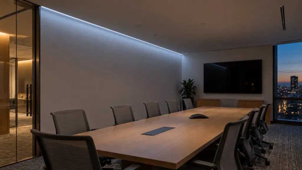
Label every decoder with its short address and group on the drawing and in the run register, beside the supply it hangs from. When a decoder fails, the replacement takes the same address and limits only if someone wrote them down. Put the full set, address, groups, physical limits, operating range, scenes, power-on and failure levels, into the handover file our commissioning and handover checklist describes, so the next technician can rebuild a decoder from paper rather than from guesswork.
Before You Order
- Strip, decoder and supply are all 24V constant-voltage; no constant-current DT8 drivers.
- Decoder load at both channels full, under 288 W for a 360 W decoder.
- Address count per line from the supply layout, with spare addresses left.
- DALI pair run with line-voltage methods, kept apart from Class 2 strip leads.
- Front end confirmed to send Part 209 Tc commands.
- Physical limits 2700/6500K, operating range per space, power-on and failure levels per space.
Unitop Lighting supplies tunable white LED strip in 2835, COB and CSP builds and the UT-CDALI-DT8 controller and supplies on our drivers and controllers page. Send the reflected ceiling plan with the zones marked and we will return the decoder count, the supply layout and the address total per line with the quote: request a quote.