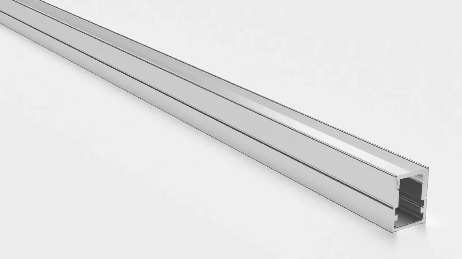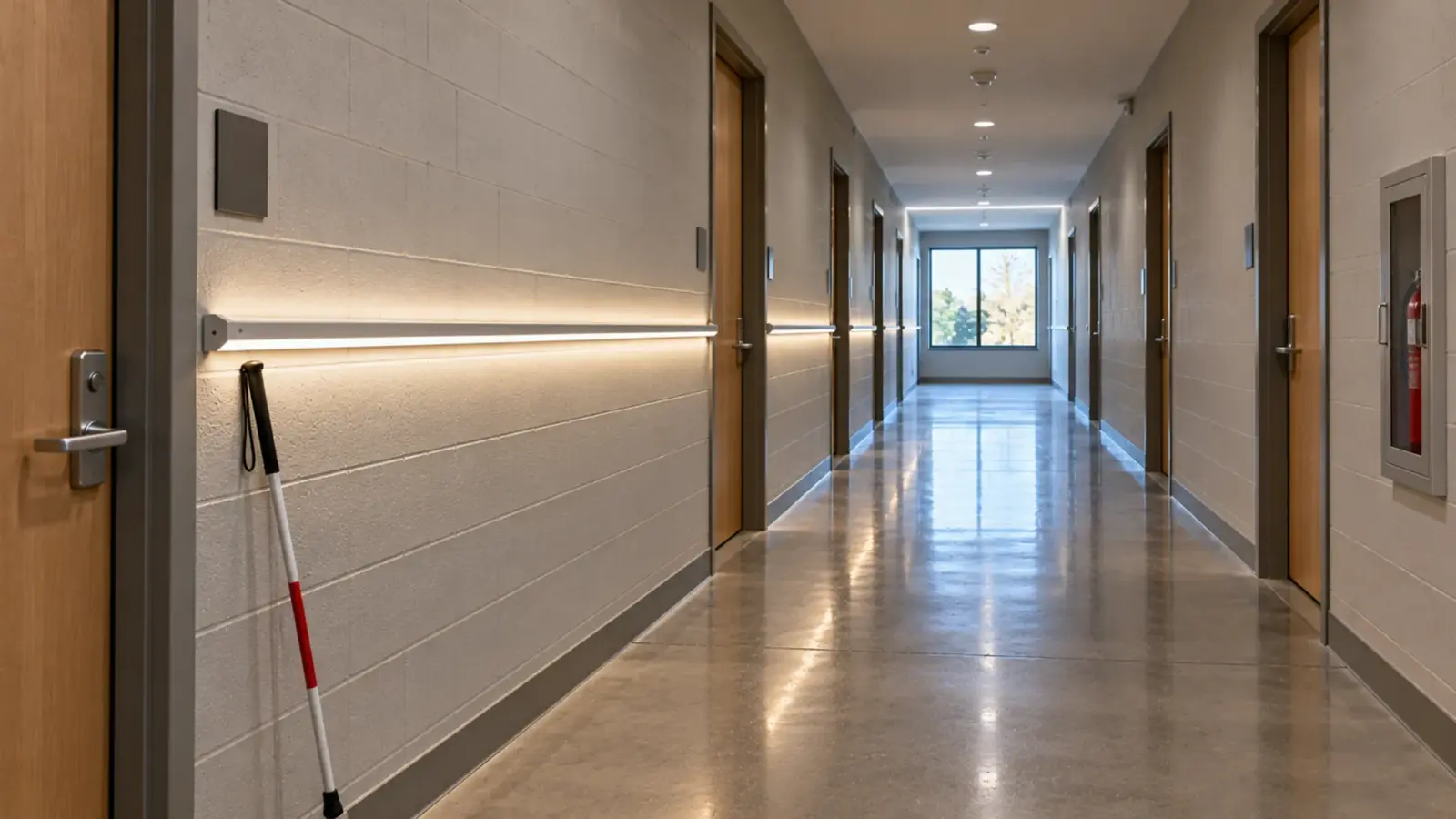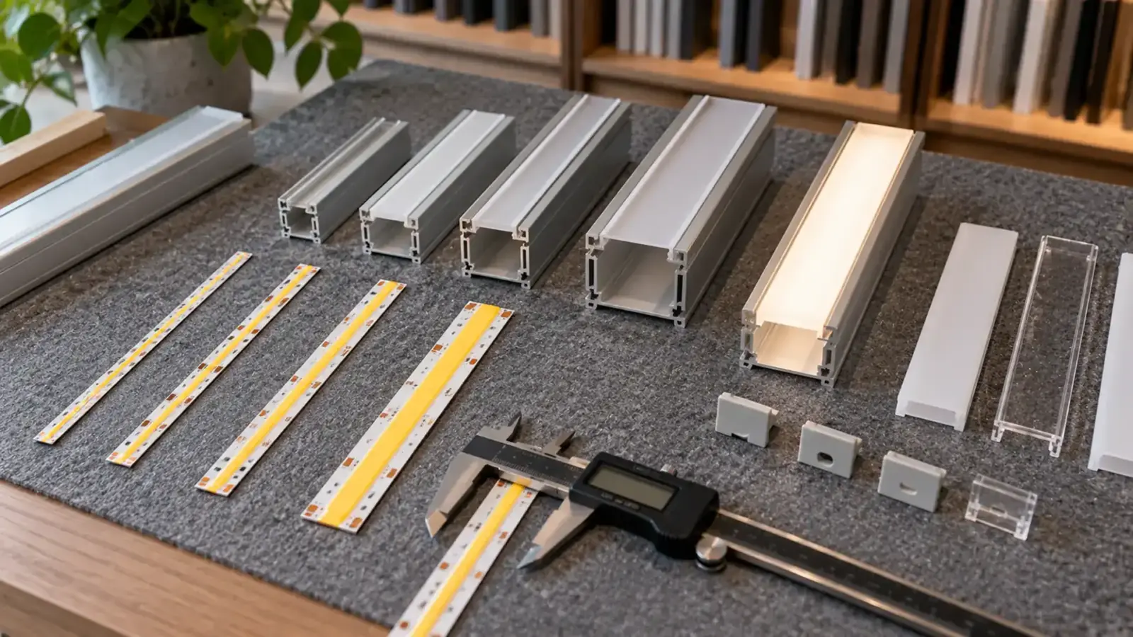
A 12 mm strip fits a channel rated for 12 mm strip. Add a soldered feed and a cable leaving through the end cap, and the same channel may not close. Channel fit is three checks: the strip’s real width, the room a joint or cable needs, and the depth above the strip.
The fit table below uses the widths of the strips we make and the maximum strip width each of our channels is rated for. The method works for any strip and any channel; the numbers are ours.
Measure the PCB, Not the Product Name
Strip is sold by a nominal width, and the nominal width is usually right for a bare board. It is not right for everything else:
- IP-rated strip has a silicone coating, sleeve or tube around the board, and the outside of that is what has to fit.
- Dual-row strip carries two rows of LEDs on a wider board.
- Connectors and solder joints sit on top of the board and are often wider than it.
Measure a cut sample with calipers: the board width, the total width including any coating, and the height including the LEDs. For a channel, look for the rated maximum strip width or the internal width on the drawing; Top LED Profile’s guide makes the same point that the outside size of the profile tells you little.
Checkpoint: write the measured width and height of the actual strip on the schedule next to the channel model.
Strip Widths We Make
| Family | Widths on our spec tables | Examples |
|---|---|---|
| COB, narrow | 2.7/3 mm, 4/5 mm, 5 mm | UT-C400-3, UT-C400-5, UT-C400-5-LV |
| COB, compact | 6 mm, 6.5 mm, 6.6 mm, 7 mm | UT-C320-6-SV, UT-C300-6, UT-C320-6-SF, UT-C480-7 |
| COB, standard | 8 mm, 10 mm | UT-C320-8, UT-C480-8, UT-C512-10 |
| COB, wide | 12 mm dual-row, 15 mm, 30 mm | UT-C600D-12, UT-C960-15, UT-C1600-30 |
| SMD | 4/5 mm, 8 mm, 10 mm, 12 mm | UT-S2835-120-UN, UT-S2835-60, UT-S2835-120, UT-S5050-120 |
| CSP, bare | 8 mm | UT-CSP-320-N (8 × 1.85 mm profile) |
| CSP, IP68 | 10 × 5 mm, 12 × 5 mm profiles | UT-CSP-320-68, UT-CSP-540-RGB-68 |
| Tunable white | 6.6 mm, 8 mm, 10 mm | UT-T480-7, UT-T576-8, UT-T640-10 |
Most commercial work lands in the 8 mm and 10 mm rows. The narrow COB strips exist for small profiles and millwork; the wide COB strips are high-output strip for coves and indirect light where the channel is chosen around them.
The Fit Table: Strip Width vs Channel Rating
Each of our channels has a rated maximum strip width. A strip fits when its width, including any coating, is at or below that number.
| Channel | Type | Size (W × H) | Max strip | Fits our |
|---|---|---|---|---|
| UT-CH1207 | Surface, compact | 12 × 7 mm | 8 mm | 3 to 8 mm strip |
| UT-CH1013 | Surface, slim | 13 × 10 mm | 10 mm | Up to 10 mm |
| UT-CH1708 | Recessed, flanged | 17 × 8 mm | 10 mm | Up to 10 mm |
| UT-CH1616 | Corner, 45° aim | 16 × 16 mm | 10 mm | Up to 10 mm |
| UT-CH1715 | Recessed, flanged | 17 × 15 mm | 12 mm | Up to 12 mm, incl. 12 mm dual-row |
| UT-CH2020 | Plaster-in, trimless | 20.2 × 19.5 mm | 12 mm | Up to 12 mm |
| UT-CH2415 | Surface, deep dot-free | 24 × 15 mm | 15 mm | Up to 15 mm, incl. UT-C960-15 |
| UT-CH3020 | Surface, wide | 30 × 20 mm | 20 mm | Up to 20 mm |
Read it from the strip side and the choice narrows fast:
- 8 mm strip fits every channel in the range.
- 10 mm strip fits all but UT-CH1207.
- 12 mm strip (SMD 5050, dual-row COB, IP68 CSP RGB) needs UT-CH1715, UT-CH2020, UT-CH2415 or UT-CH3020.
- 15 mm strip needs UT-CH2415 or UT-CH3020.
- 30 mm strip (UT-C1600-30) is wider than any channel in the standard range; its channel is matched at quote.
Leave Room for the Joint and the Feed
A channel rated for 12 mm strip holds a 12 mm board. It does not promise room for what sits on the board at the ends and at the joints. VST Lighting describes exactly this case: a 12 mm COB strip plus its feed cable crowding the end-cap area of a profile chosen for 12 mm strip.

Three places to check:
- The feed end. A soldered lead or a wire-to-strip connector adds height and often width; the cable has to turn and leave through the end cap or the back of the channel.
- Joints mid-run. A strip-to-strip connector’s housing is usually wider and taller than the strip. Our connector table lists strip-to-strip, wire-to-strip and strip-wire-strip connectors for 8, 10 and 12 mm boards, and a PCB corner connector for 8 and 10 mm.
- Corners. A corner connector or a soldered jumper needs space at the mitre.
When a joint or a feed has to sit inside the channel, choose the next size up, or plan the joint where the channel is open, at an end or behind an access point. Our connector guide covers which joint suits which space.
Checkpoint: dry-fit the actual feed end and one joint in a short piece of the channel, with the cover on, before ordering the full length.
Jacketed and IP Strip Is Wider
Coating and sleeving add width and height. Our IP68 CSP strip makes the difference visible: the bare UT-CSP-320-N is an 8 × 1.85 mm profile, while the IP68 UT-CSP-320-68 is 10 × 5 mm and the IP68 RGB UT-CSP-540-RGB-68 is 12 × 5 mm. A channel chosen for the bare strip will not take the jacketed one.
Waveform Lighting gives the same advice from the other side: waterproof and RGBW strips around 12 mm wide need a channel wider than 12 mm. For IP65 and Dust-tight, and protected against temporary immersion in water. The usual rating for wet or outdoor runs that are not submerged all the time. strip whose outside width is not on the spec table, measure a sample.
Height matters too. A 5 mm tall jacket in a shallow channel sits close to the cover, which changes how the cover diffuses the light; see our diffuser guide.
When a Wider Channel Is Worse
Wider is not always safer.
- The strip wanders. A 3 mm strip in a channel rated for 8 mm has room to drift sideways. Behind a clear cover or in a long slot, a line that wanders a millimeter reads as a wavy line.
- The adhesive needs a full floor. Strip adhesive should sit flat across its whole width. A channel with a ribbed or narrow floor under a wide strip leaves the edges unsupported.
- The look changes. A wide opal cover over a narrow strip shows a narrow bright stripe down a wide diffuser, not an even face.
For narrow strip, use a narrow profile or a guide that centers the strip, and check straightness in a mockup with the cover on. Where a narrow strip has to go into a standard channel, a strip of double-sided tape or a thin spacer along one wall keeps the line straight; mark the centerline on the channel floor before the strip goes in, so every length follows the same line.
Depth Is a Separate Check
Width decides whether the strip goes in. Depth decides whether the cover hides the LEDs and whether there is room above a joint. A shallow channel such as UT-CH1207 (7 mm high) keeps a slim line; a deep one such as UT-CH2415 (15 mm high) gives the cover distance to blend the LEDs into one line. Our channel selection guide goes through depth and mounting type, and our guide to whether LED tape needs a channel covers heat and code.
Final Checks
- Strip width measured on a sample, including any coating
- Channel’s rated maximum strip width at or above it
- Feed end and one joint dry-fitted with the cover on
- Corners and end caps checked for connector space
- Narrow strip centered and straight in a wide channel
- Depth enough for the cover to hide the LEDs
The rated maximum strip width for each profile is listed on our LED channels and diffusers page.