A An analog dimming standard: a two-wire control signal from 0 to 10 volts sets the level on a compatible driver. Simple and common in commercial work; it needs a driver with a 0-10V input. wall dimmer carries a few milliamps of control current and switches nothing unless it has a relay inside. Every 0-10V LED dimming wiring diagram below follows from those two facts: the driver keeps its own line feed, the dimmer only pulls the control pair down, and turning the zone off is a separate job.
Use the diagrams in order. The first is one driver; the second is a whole zone with the limits that come with it; the third adds a 3-way, a sensor and a decoder. To choose between 0-10V, phase-cut and DALI in the first place, start with our dimming method guide.
How the Pair Works: Source, Sink, Open and Short
The two dimming leads on the driver carry a DC control signal, not power. The driver sources a small current onto the pair and the dimmer sinks it, pulling the voltage down; the Hatch Lighting 0-10V technical guide describes the driver as the current source and the dimmer as the current sink. Our dimming method guide reads IEC 60929 Annex E as full output at 10V, minimum at or below 1V, and a control current between 10 µA and 2 mA per driver.
Two consequences decide how a zone fails:
- An open pair means full output. With nothing pulling the voltage down, the driver sees 10V. A broken lead, a loose wire nut or a dimmer that was never connected leaves the zone stuck at full.
- A shorted pair means minimum, not off. ETC’s support note on non-dimming fixtures says that with the pair shorted the fixture should go to its minimum intensity, and with the pair open it should go to full. Minimum is the driver’s lowest level, which may still be visibly on.
That is why a 0-10V zone needs a second path for off: a relay in the dimmer, a separate relay or power pack, or a driver that can dim to off while it stays powered.
Wire Colors: Violet and Pink, or Violet and Gray
Older drivers and dimmers mark the pair violet (+) and gray (−). Newer products use violet and pink, because gray is the color the NEC reserves for grounded conductors; the Hatch guide lists violet and pink as +DIM and −DIM, and Electrical Contractor magazine has reported the change as NEMA guidance following the 2020 NEC, effective January 1, 2022.
On a job that mixes the two, the label on each driver decides, not the color. Join violet to violet, and gray to pink only when both labels say they are the negative lead. A reversed pair can leave a zone at full or not dimming at all. Mark the color pair on the panel schedule so the next electrician does not have to guess.
Diagram 1: One Driver, One Dimmer With a Relay
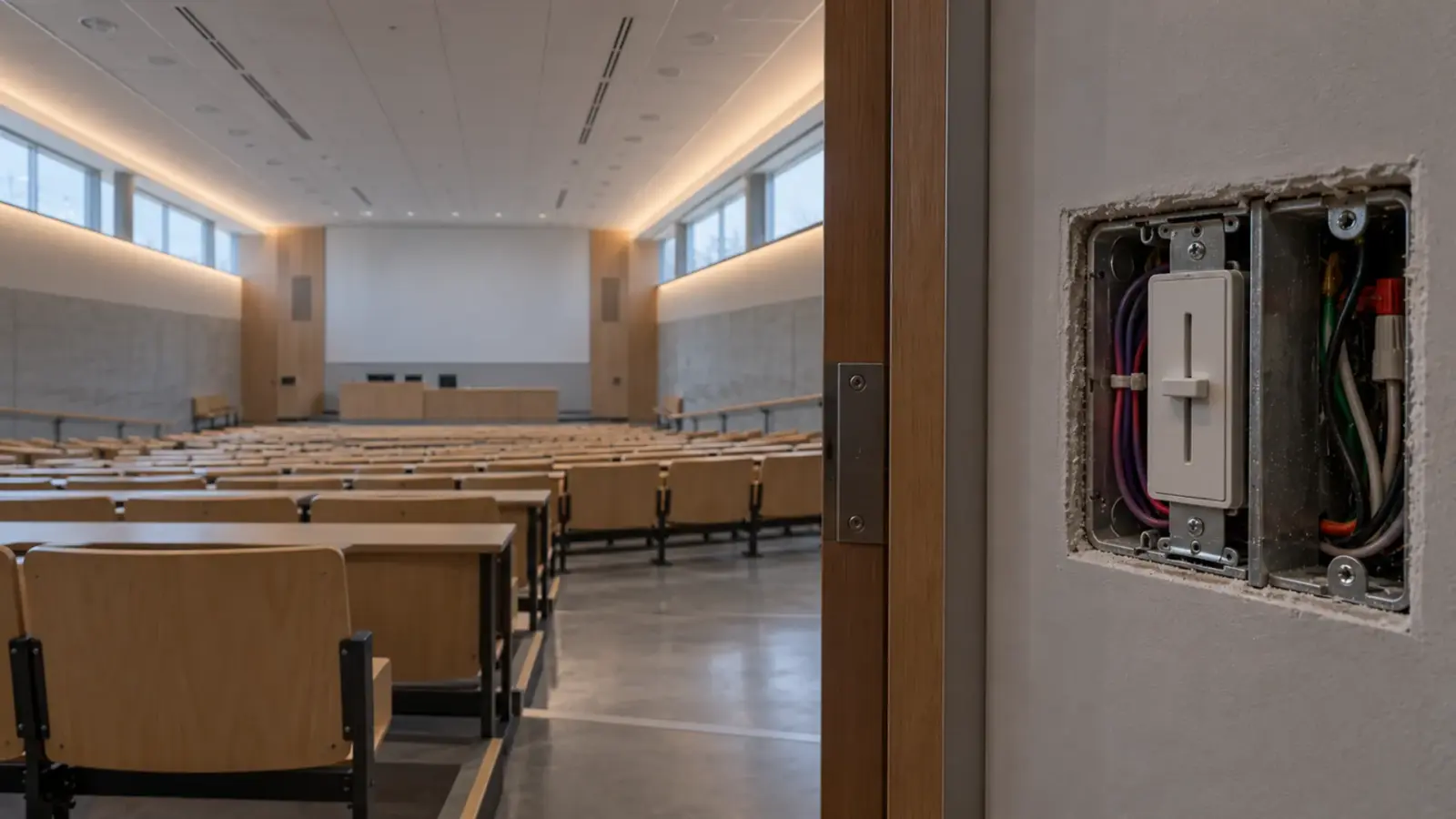
The simplest circuit is one dimmable driver, one 0-10V wall dimmer with an internal relay, and a strip.
- Line side: hot from the panel to the dimmer’s line terminal, the dimmer’s switched leg to the driver’s line input, neutral to the driver, ground to both.
- Control side: violet from the dimmer to the driver’s violet, pink or gray from the dimmer to the driver’s matching lead.
- Output: the driver’s 24V output to the strip, inside the strip’s run limit per feed.
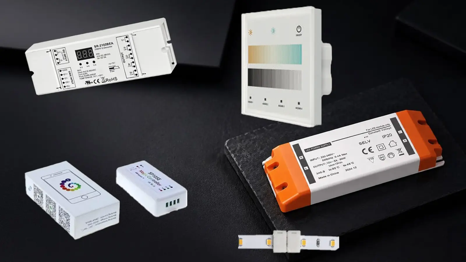
Our UT-D60-24-C2-010 fits this circuit: a 60 W, 24V driver with a 120–277V input and 0-10V dimming, in our Class 2 group. The relay in the dimmer gives a true off; without one, the dimmer’s lowest setting is the driver’s minimum. Our UT-CTP-010 0-10V touch panel takes a 100–277 VAC supply and runs one zone; it sends the control signal only, so its own feed is part of the wall box wiring and the off comes from a relay elsewhere in the circuit.
Checkpoint: before the device goes in, confirm the dimmer has a relay rated for the load, or show a separate relay on the plan.
Diagram 2: One Dimmer, a Whole Zone of Drivers
Most commercial zones put several drivers on one dimmer: a corridor cove, a classroom perimeter, a lobby slot. The control pair runs in parallel to every driver, violet to violet and negative to negative, and the line side runs to every driver through the relay. Two limits set how many drivers one dimmer can take.
Limit 1: the dimmer’s sink current. Each driver sources up to 2 mA onto the pair under the IEC reading above, and the dimmer has to sink the total. Lutron’s spec sheet for the Diva DVSTV 0-10V dimmer gives a 50 mA maximum control current and counts that as up to 25 ballasts or drivers at the 2 mA IEC limit. Use the driver maker’s actual source current where it is published, and the 2 mA ceiling where it is not.
Limit 2: the relay’s current and the inrush. The same spec sheet rates the DVSTV at 8 A, for drivers whose inrush meets NEMA 410. Running watts are rarely the problem; the inrush of every driver starting at once is, which our inrush guide covers.
A typical corridor zone, worked:
| Item | Value |
|---|---|
| Drivers | 10 × UT-D60-24-C2-010, each loaded to its 60 W rating at most |
| Control current (worst case) | 10 × 2 mA = 20 mA, inside a 50 mA dimmer |
| Input power per driver | 60 W ÷ 0.85 efficiency ≈ 70.6 W |
| Zone input power | ≈ 706 W |
| Steady current at 120V | ≈ 5.9 A, inside an 8 A rating |
| Steady current at 277V | ≈ 2.5 A |
The currents assume a power factor near 1; at 0.9 they rise to about 6.5 A at 120V and 2.8 A at 277V, still inside 8 A.
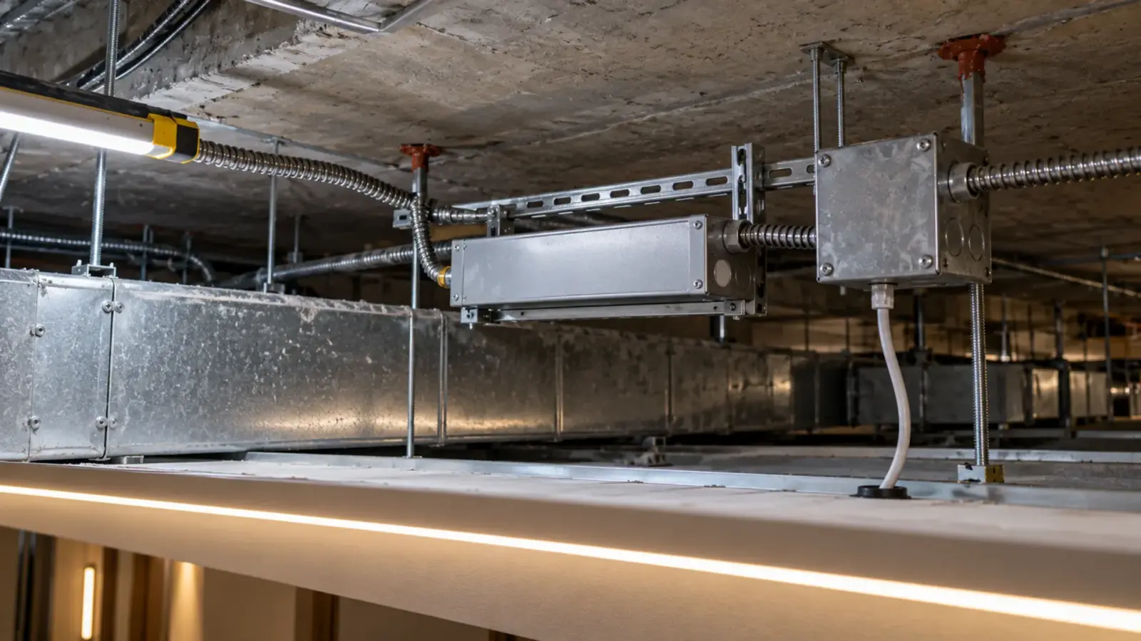
The control side has room for more drivers; the relay side at 120V does not have much. On a larger zone, put the drivers on a separate relay or power pack sized for their The brief surge a driver draws at switch-on while its capacitors charge, many times its running current. Several drivers on one breaker can trip it at power-up. and let the wall dimmer carry only the control pair. One maker’s installation guide also caps the total 0-10V control wiring for its dimmer at 500 ft, with no wire smaller than 20 AWG, so check the length and gauge limits on the dimmer you use.
How the pair travels through the zone matters as much as the count:
- Parallel, not series. Every driver’s violet lands on the same violet conductor and every negative on the same negative. A driver left off the pair runs at full while the rest dim.
- One pair per zone. Our dimming method guide makes the point that every driver on one pair dims together, and that the small signal wires look identical in a ceiling. Keep a schedule of which drivers share which pair, and tag the pair at each driver.
- One driver family per pair. Drivers from different makers can follow different dimming curves on the same signal, so two of them side by side at 30% may not match. Mix them only after a bench test on the real strip.
- Splices where they can be reached. Land the pair in the driver’s wiring compartment or in an accessible box, not in a buried splice above a hard ceiling.
Checkpoint: write the driver count per zone on the plan, with the dimmer’s sink rating and the relay’s rating next to it.
Diagram 3: Three-Way, Sensors and a Decoder on the DC Side
Three circuits come up after the basic zone.
Three-way. Lutron’s spec sheet describes the Diva DVSTV as a single-pole or 3-way device: it works with a standard mechanical 3-way switch at the second location, and the dimming happens only at the dimmer. Where both doors need dimming, use a system with multi-location controls rather than two 0-10V dimmers on one pair.
Occupancy sensors. A sensor can switch the drivers’ line feed through a relay, or a controller can dim the zone and keep the drivers powered. Our occupancy sensor guide works through which one the space needs.
A decoder on the DC side. When a job already has non-dimming drivers, a 0-10V decoder sits between the driver’s output and the strip. Our UT-C010-350 takes 12–24V DC in, handles up to 350 W on one channel, and reads a 0-10V signal. With a UT-D60-24-C2 non-dimming 60 W An NEC Article 725 output class limited to 100 VA at up to 60 V DC, with the wiring relief that comes with it. Our Class 2 drivers are rated 60 W; a bigger load needs more outputs or a non-Class 2 driver. driver ahead of it, the driver’s 60 W is the limit for that strip, not the decoder’s 350 W. The control pair then lands on the decoder instead of the driver.
Checkpoint: for a 3-way, mark which location dims and which only switches. For a decoder, check that the driver, the decoder and the strip share one voltage.
Which Diagram Fits Which Space
The space usually picks the diagram before anyone opens a catalog:
| Space | Usual circuit | Why |
|---|---|---|
| Hotel guest room cove or headboard | Diagram 1, or a zone on the room controller | One driver per zone; the controller sets the night level |
| Classroom or office perimeter | Diagram 2 with an occupancy sensor (Diagram 3) | Several drivers per zone; the energy code asks for automatic off |
| Long corridor cove | Diagram 2 with a separate relay or power pack | Many drivers; inrush outgrows a wall-box relay |
| Lobby slot with non-dimming drivers already installed | Decoder on the DC side (Diagram 3) | Dimming is added without replacing the drivers |
| Amenity room with two doors | 3-way (Diagram 3) | One location dims, the other switches |
When the space has a lighting control system, the zone usually lands on that system’s 0-10V output instead of a wall dimmer, and the same two limits apply to the output: its sink rating and the relay that switches the drivers.
Class 1 or Class 2: Where the Pair May Run
The control pair is low voltage, but low voltage does not make it Class 2. Our dimming method guide notes that whether the 0-10V pair counts as Class 2 depends on how the driver is marked, and the control has its own rating too: Lutron’s spec sheet lists the DVSTV’s 0-10V control link as Class 1, and one maker’s installation guide gives separate Class 1 and Class 2 wiring diagrams for its dimmer. Class 2 conductors generally may not share a raceway, enclosure or cable with line-voltage or Class 1 conductors, apart from listed exceptions such as barriers.
On a job, that means three things:
- Read both the driver’s label and the control’s spec sheet for the class of the pair before it is pulled. If either side is Class 1, wire the pair as Class 1.
- Keep a Class 2 pair out of the feed’s conduit unless an exception in the adopted code applies; a two-gang box with a barrier keeps the line and the pair apart at the wall.
- Use cable rated for the space. Our in-wall wiring guide covers CL2, CL3 and plenum cable.
Confirm each point with the AHJ and the NEC edition the area has adopted.
Test Before Handover
Test each zone with the strip connected, before the ceiling closes. A meter across the pair and the two tests from the first section find most faults.
| Test | Expected | If not |
|---|---|---|
| Dimmer at full | About 10V across the pair, strip at full | Low voltage at full: a shorted pair or a dimmer sinking too much |
| Dimmer at minimum | 1V or less, strip at its lowest level | Strip still bright: pair not landed, or reversed |
| Pair disconnected at the dimmer | Strip goes to full | Strip dims or goes dark: the pair is shorted downstream |
| Pair shorted at the dimmer | Strip goes to minimum | Strip stays at full: an open lead between dimmer and driver |
| Dimmer turned off | Relay opens, strip dark | Strip glows: no relay, or the driver’s minimum is on |
| Every driver in the zone | Same level at each step | One driver at full: its pair is open or reversed |
Record the readings per zone. Our compatibility test guide covers the bench test to run before the order.
Final Checks
Each zone on the plan should show the driver model and count, the dimmer’s sink rating, the relay or power pack and its rating, the color pair, and the class of the pair from both the driver label and the control’s spec sheet. The driver’s output should stay within the strip’s run limit per feed, and every zone should have a recorded open, short, full and off test.
The drivers, the decoder and the wall panel named here are on our drivers, controllers and connectors page.