You have a Strip under the base of cabinets or furniture, lighting the floor. A low-brightness, usually motion- or dimmer-controlled application. about 3.5 in tall, a vanity that housekeeping mops every night, and a plan that says “night path, motion”. Toe kick lighting with a motion sensor works when the strip is sealed and set back, the sensor switches the low-voltage side of a driver outside the kick, and the timeout is commissioned.
The six steps below follow that order, each with the check to make before moving on.
Step 1: Decide What the Night Path Lights
A toe kick light lights the floor, not the room. Its job at night is to show a guest or a resident where the floor is between the bed and the bathroom without waking anyone else, so the line should be low, dim and out of sight. Our hotel guest room guide places it under the bed base, under the vanity and along toe kicks; our senior living guide keeps night lighting no higher than 2 ft above the floor on the same route.
The four places a motion-switched toe kick usually earns its cost on commercial and multifamily work:
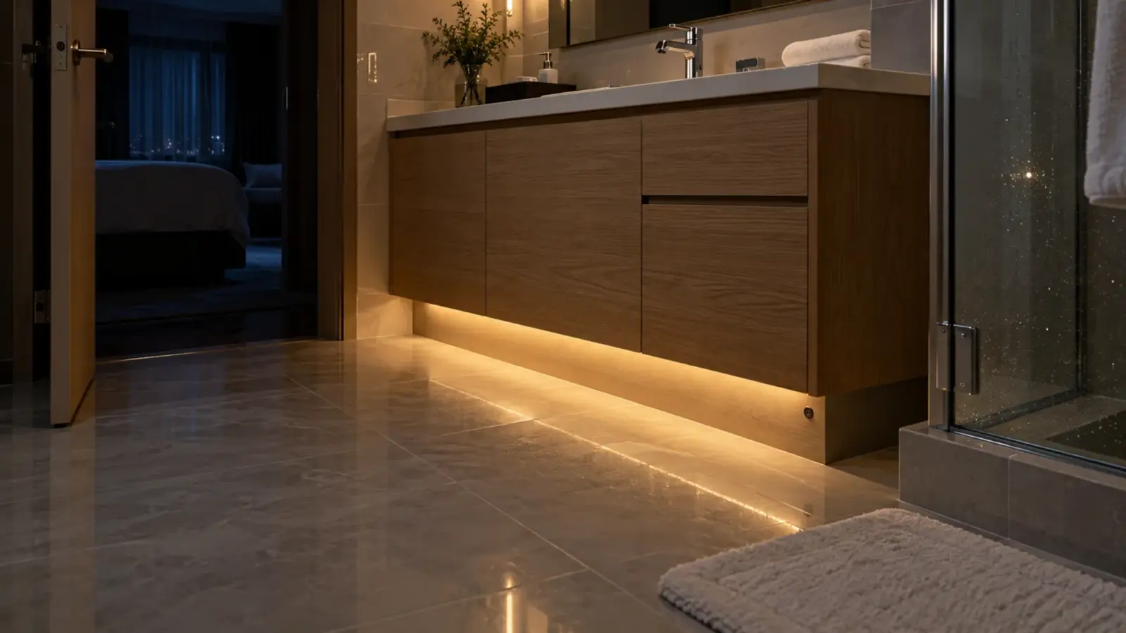
- Hotel guest bathroom vanity: the first thing a guest walks to at night.
- Wardrobe or entry millwork in a guest room: the start of the path from the bed.
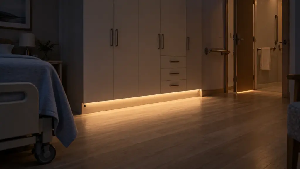
- Senior living bathroom and wardrobe: the same route, with falls at stake and staff who should not have to touch a switch.
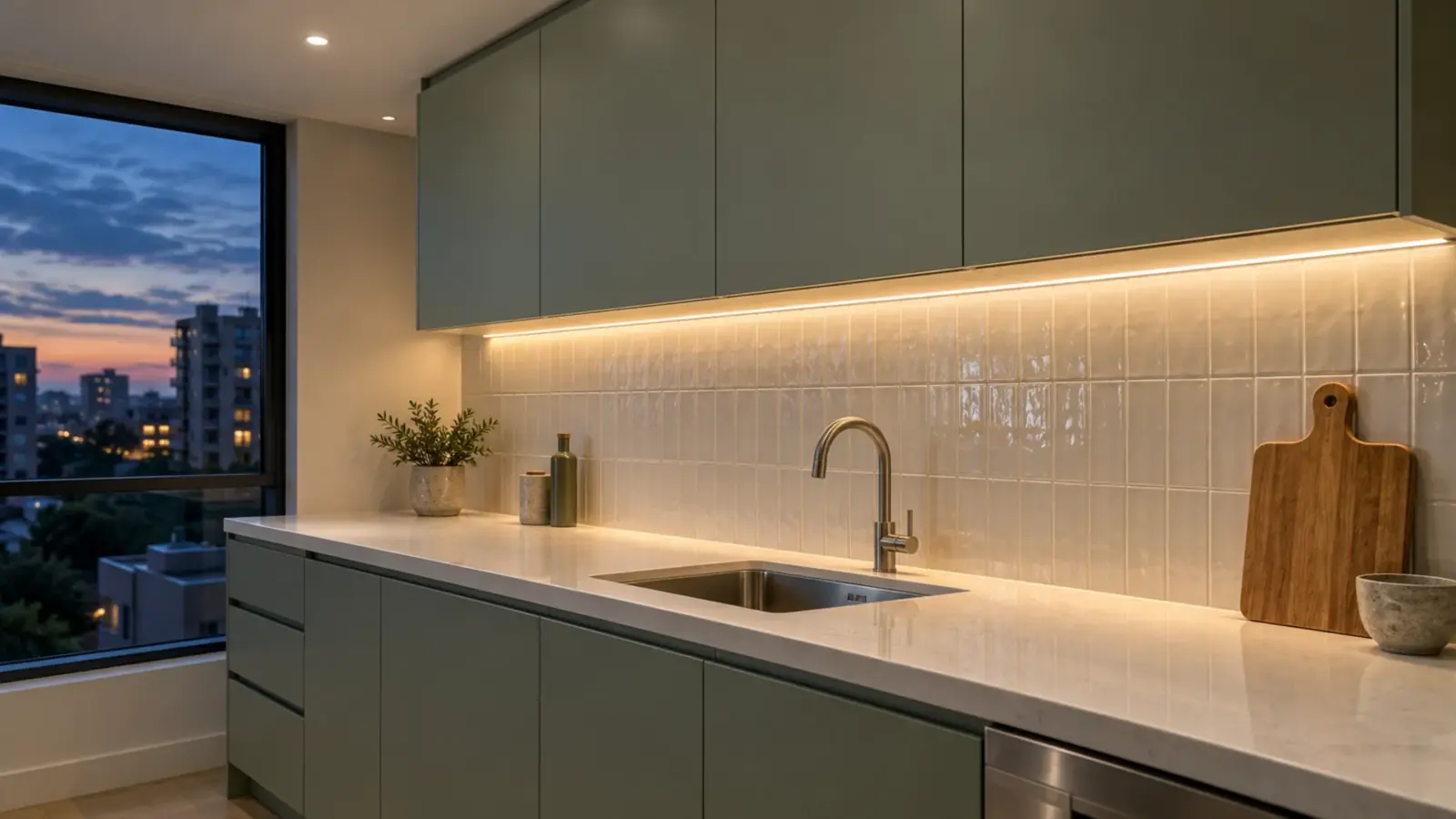
- Apartment kitchen base cabinets and islands: a late-night glass of water without the downlights on.
Checkpoint: mark on the plan which toe kicks are on the night path and which are decorative. Decorative toe kicks can sit on a normal switch or a scene; only the path needs a sensor.
Step 2: Detail the Kick: Height, Set-Back and a Mop-Proof Strip
Draw the toe kick lighting detail before the millwork shop builds the boxes, because the space is small and fixed. Retail cabinet guides put the usual toe kick at about 3.5 in high and 3 in deep, with many lines at 4 to 4.5 in high; the shop drawing for your casework is the only number to trust.
| Part | Where it goes | Why |
|---|---|---|
| Channel | Underside of the cabinet base, just behind the front edge, or in the top inside corner of the recess | The cabinet edge hides the line from standing height; only the wash on the floor shows |
| Lens | Opal | A clear lens shows each LED as a dot in a polished floor |
| Strip | Silicone-coated, sealed ends, leads exiting upward | Mop water reaches the kick every night |
| Sensor | Drilled into the kick face or under the base edge, at the end of the run where the first foot arrives | It has to see a foot, not the room |
| Driver | Outside the kick: inside a ventilated cabinet, above the ceiling or in a closet | Heat is trapped in a kick and access means pulling a panel |
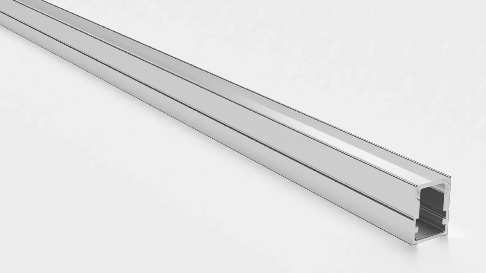
Two of our channels fit this space. The UT-CH1616 corner channel is 16 × 16 mm (0.63 × 0.63 in), aims at 45° and takes a strip up to 10 mm wide; in the inside corner of the recess it throws the light down and forward onto the floor instead of into the back of the kick. The UT-CH1207 surface compact channel is 12 × 7 mm (0.47 × 0.28 in) and takes up to 8 mm, which suits a bare 8 mm strip in a dry kick; a silicone-coated strip can come out wider than its 8 mm board, so check the coated width against the channel at quote.
For the strip, our UT-O320-8-65 has a silicone top coat rated IP65, draws 2.4 W/ft and runs 16 ft (5 m) from one feed. It is a COB strip, so its reflection in a polished stone or vinyl floor reads as one line rather than a row of dots, which matters more at floor level than in a ceiling cove. Our under-cabinet and millwork page says the same about mopping: use a silicone-coated strip with sealed ends where cleaning water can reach, and keep the driver out of the toe kick.
Checkpoint: before the boxes are built, confirm the kick height and depth on the shop drawing, the channel position, the sensor hole and the route of the lead up into the cabinet.
Step 3: Pick the Sensor Wiring: DC Side, Line Side or the Room Controller
This is the decision a senior electrician asks about first, because it decides what the relay sees, whether the driver stays powered, and where the An NEC Article 725 output class limited to 100 VA at up to 60 V DC, with the wiring relief that comes with it. Our Class 2 drivers are rated 60 W; a bigger load needs more outputs or a non-Class 2 driver. boundary sits. There are three ways to put toe kick lighting on a motion sensor.
| DC-side sensor switch | Line-side occupancy sensor | Night zone on the room controller | |
|---|---|---|---|
| Where it sits | Between the Class 2 driver’s output and the strip | Ahead of the driver, on the 120V or 277V feed | A zone of the guest room control system, with its own vacancy or motion input |
| What switches | Low-voltage DC to the strip | The driver’s input | The driver’s 0-10V signal, or a relay per zone |
| Driver | Stays powered; small standby draw | Starts from cold at every trigger | Stays powered when dimmed to off |
| Relay sees | Strip current only | Driver inrush at every trigger | Depends on the controller: dim or relay |
| Night level | On/off, sometimes with soft start | On/off | Any level the controller sets |
| Who installs | Millwork shop or low-voltage installer, inside the casework | Electrician, in a wall box | Controls contractor, programmed with the room |
| Fits | Vanities, wardrobes and kitchens with their own small driver | Rarely the best fit for a toe kick | Hotels and senior living with room controls |
For a single vanity or kitchen run, the DC-side switch is our recommendation. The driver stays on, the sensor only breaks a small DC current, and the switching happens inside the casework where the strip already is. A line-side sensor switching a driver fires the driver’s inrush at every trigger; our occupancy sensor guide explains how repeated inrush can weld relay contacts. A night path triggers many times a night in a busy room. A two-wire line-side sensor, like a two-wire dimmer, can also pass a small leakage current that makes a driver flicker or glow when the strip should be dark; our glow-when-off guide covers that fault, including leakage across a DC-side switch.
Where the building has guest room controls, the toe kick should usually be a zone on that system rather than a stand-alone sensor. Then the night level, the timeout and the master off are set in one place, and the toe kick behaves like the rest of the room.
Checkpoint: write the chosen architecture on the lighting plan, with the driver model and the sensor model, so the millwork, electrical and controls trades read the same thing.
Step 4: Place and Aim the Sensor
A toe kick sensor sits about 3 in off the floor and looks along it, so it sees feet, ankles and anything else that moves at that height. Place it so the first step toward the path triggers it, and so nothing else does.
- At the arrival end. One poster on a home-automation forum planned a sensor in the vanity toe kick about 6 in inside the bathroom entry, to bring up the mirror lights as someone walked in. The same logic holds for a night path: put the sensor where the foot arrives, not in the middle of the run.
- Not facing the bed. A sensor that can see the edge of the bed fires when a sleeper’s arm or blanket moves. In a guest room, aim the wardrobe sensor along the wall, not across the room.
- Not facing the corridor door. Feet passing in the corridor can show through the gap under the door.
- Away from floor registers. A passive infrared sensor reacts to moving warmth, so keep the lens out of the air stream from a floor or toe-kick register and test it with the heat running.
- Read the cone. One cabinet-lighting sensor line, Häfele’s Loox modular detector, is listed by a UK retailer with a 0 to 3,000 mm (about 10 ft) range, a 90° horizontal by 120° vertical cone and a 12 mm drill hole; check the maker’s data sheet for the model you buy. A cone that wide reaches across a small bathroom, so aim matters more than range.
Checkpoint: mock up one room. Lie in the bed, turn over, and walk the corridor outside with the room dark. The toe kick should stay off for all three and come on at the first step toward the bathroom.
Step 5: Size the Driver and Check the Sensor’s Current
A night path is a small load, which is why a stand-alone toe kick driver is usually the smallest one on the job. Here is a typical guest room, with the lengths assumed for the arithmetic:
| Run | Length | Strip | Load |
|---|---|---|---|
| Vanity toe kick | 5 ft | UT-O320-8-65 at 2.4 W/ft | 12.0 W |
| Wardrobe toe kick | 4 ft | UT-O320-8-65 at 2.4 W/ft | 9.6 W |
| Total | 9 ft | 21.6 W |
At 24V, 21.6 W is 0.9 A. A UT-D40-24-C2 Class 2 driver at 40 W carries it at 54% of its rating, inside the 80% headroom our power supply sizing guide keeps. The DC-side sensor switch then has to be rated for at least 0.9 A at 24V (about 22 W); read its rating in amps at the strip voltage, not the wattage on the box for a different voltage.
An apartment kitchen shows where the arithmetic bites. Take 14 ft of base-cabinet and island toe kick with the same strip: 14 × 2.4 = 33.6 W. On the 40 W driver that is 84%, over the 80% line, so the job takes the 60 W UT-D60-24-C2 (56%) or two drivers. The run is still inside the strip’s 16 ft single-feed limit.
Two runs on one driver need one sensor switch rated for both, or one switch per run. If the vanity and the wardrobe should come on separately, give each its own switch on the DC side; the driver can stay shared.
Checkpoint: list every toe kick on the night path with its length, load, driver and sensor rating. The driver location goes on the electrical plan, never inside the kick.
Step 6: Commission the Timeout and the Night Level
A toe kick that comes on at full output at 2 a.m. defeats its purpose, and one that stays on all night costs a callback. Commissioning sets both.
- Timeout. Stand-alone cabinet sensors often offer a few fixed delays; the same retailer lists the Häfele modular detector above with 5, 15 and 30 minutes. A night path usually takes the shortest delay that still covers a bathroom visit.
- Night level. A DC-side switch is on or off, so the level is set by the strip’s output and the lens. For a lower level, use a dimmable driver such as our UT-D60-24-C2-010 in a controller zone, so the night path can sit at a fraction of full output.
- Guest room controls. Our guest room controls guide reads the ASHRAE 90.1-2016 summaries as a master off 20 minutes after the room is vacant and a separate bathroom off at 30 minutes. According to an Energy Trust of Oregon training deck on 90.1-2016, the bathroom exception covers night lighting of no more than 5 W. The 5 ft vanity run above draws 12 W, so it cannot be that night light and should follow the bathroom off; about 2 ft of this strip fits under 5 W. Confirm against the adopted code text.
Checkpoint: in the mockup room, check the timeout with a stopwatch, the night level from the bed, and that the master off or the vacancy timer turns the toe kick off when the room empties.
When It Misbehaves
| Symptom | Likely cause | Fix |
|---|---|---|
| Comes on with nobody walking | Sensor sees the bed, the corridor door gap or a floor register | Re-aim, mask the lens, or move the sensor to the arrival end |
| Stays on all night | Delay set long, sensor in a test or “on” mode, or a welded line-side relay | Reset the delay; replace a welded sensor and move switching to the DC side |
| Glows or flickers when off | Leakage through a two-wire line-side sensor | Use a sensor with a neutral; if a DC-side switch glows, check leakage across the switch |
| Short flash or delay before it lights | Driver starting from cold behind a line-side sensor | Keep the driver powered and switch the DC side |
| Row of dots in the floor | Bare SMD strip or a clear lens over a polished floor | Opal lens, COB strip, or set the channel farther back |
| Strip dies after a few months | Uncoated strip or open cut ends in the mop line | IP65 silicone-coated strip with sealed ends and leads exiting upward |
Final Checks
Before the casework closes, the toe kick should have a channel set back behind the cabinet edge, an opal lens, a silicone-coated strip with sealed ends, a lead route up into the cabinet, and a sensor hole at the arrival end. The driver should be outside the kick and on the electrical plan, and the chosen sensor wiring should be written on the lighting plan.
The strip, channels and drivers named here are on our outdoor and waterproof LED strip page and the channel and driver pages linked above.