The cabinet shop wants an answer before it cuts the cabinet bottoms: plug-in kit, light bar, or strip built to the cabinets. The units have 30, 33 and 36 in uppers, the drawings say “Strip and fixtures fed at 12V to 48V DC from a driver, as opposed to 120V line voltage. Low voltage does not by itself mean unregulated: NEC Article 411 and Article 725 still apply. under cabinet lighting”, and the driver has to sit where a maintenance call can reach it in five years.
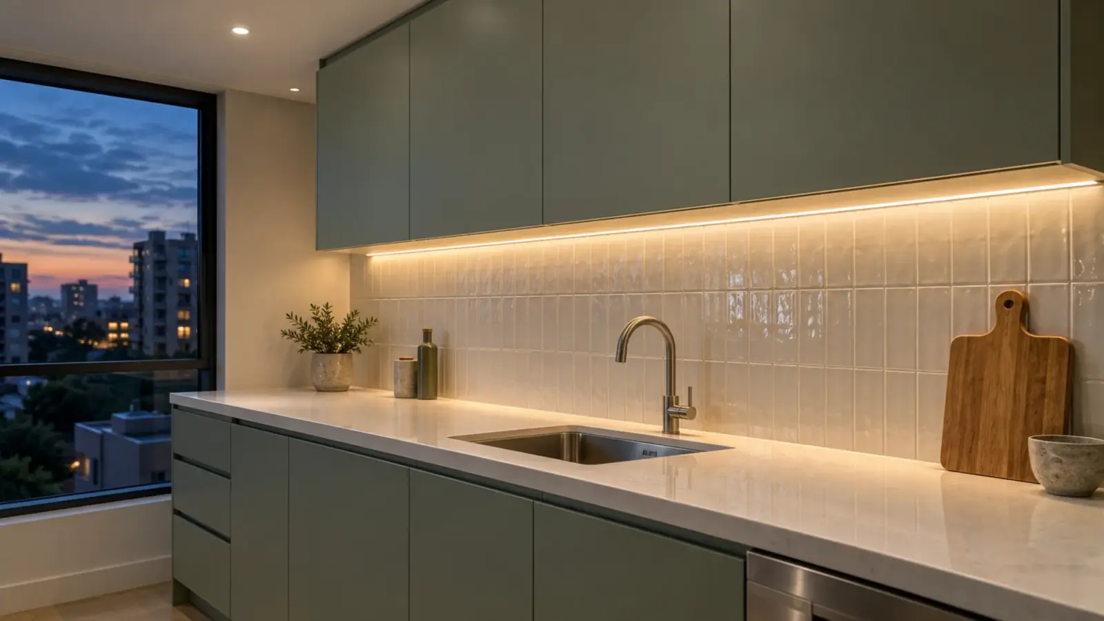
For most apartment and extended-stay hotel kitchens, the answer is 24V LED strip cut to each cabinet, in a slim aluminum channel with an opal cover, fed from a Class 2 driver on a lighting circuit, and installed before the backsplash goes in. The sections below make each call, then give the install order. The finished-space detail is on our under cabinet lighting page.
Strip, Puck or Light Bar: What Each Does to the Counter
The three formats light a counter differently. Strip in a channel throws one continuous wash. Pucks throw pools with darker gaps between them, which read as scallops on tile. A light bar lights evenly along its own length but stops where the bar stops.
| LED strip in a channel | Puck lights | Light bar | |
|---|---|---|---|
| Light on the counter | Continuous wash, end to end | Pools with gaps between | Even along each bar, gaps at the joints |
| Length | Cut to the cabinet on the strip’s cut marks | One point per puck | Fixed lengths; one 120V linkable line lists 9, 12, 18, 24, 33 and 42 in |
| Height under the cabinet | 0.39 in (10 mm) for the UT-CH1013 channel | Varies by model | 1 in for that same 120V line |
| Power | 24V DC from a separate driver | Low voltage or 120V by model | 120V on the line cited here; low voltage on others |
| Wins on | Long runs, odd widths, an unbroken line | Glass-front cabinets, open shelves, a bar back | Portfolios that stock one spare part for every unit |
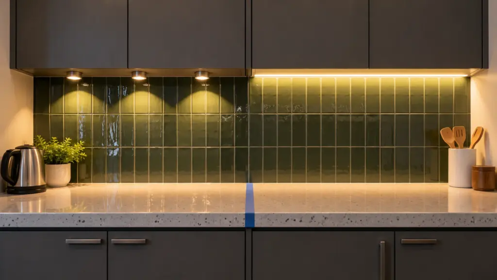
The bar’s advantage is real: a property manager who wants one spare part for 300 units may choose it on purpose, which is fair when the cabinet widths match the bar lengths.
Low Voltage or 120V Under the Cabinet
A strip can only be cut at its marks, so the last piece under each cabinet falls short of the end by whatever is left over. The table allows 1 in per cabinet for end caps and the face frame, and shows the dark length left beyond that:
| Strip | Cut increment | 30 in cabinet | 33 in cabinet | 36 in cabinet |
|---|---|---|---|---|
| UT-C480-8, 12V COB | 0.98 in (25 mm) | 0.5 in | 0.5 in | 0.6 in |
| UT-C480-8, 24V COB | 1.97 in (50 mm) | 1.4 in | 0.5 in | 1.5 in |
| UT-S2835-128-HE, 24V SMD | 2.46 in (62.5 mm) | 1.9 in | 0 in | 0.6 in |
| UT-H120-296-COB, 120V | 4.9 in (125 mm) | 4.4 in | 2.5 in | 0.6 in |
| UT-H120-60, 120V SMD | 19.7 in (500 mm) | 9.3 in | 12.3 in | 15.3 in |
Our 120V strip is built for long perimeter runs, up to 98 ft (30 m) from one feed with no driver. Under a wall cabinet three things count against it. The 19.7 in cut leaves more than a third of a 33 in cabinet dark. The 120V series lists Ra≥80 (Ra≥75 on one COB model), where the 8 mm 24V COB strips list Ra≥90. And a 120V strip is not a Class 2 product, so it is wired with line-voltage methods right at the counter, as the 120V LED strip page notes. It can suit one long run under a bar top, not a row of wall cabinets.
Between the two low voltages, choose 24V, though it cuts coarser: UT-C480-8 cuts every 0.98 in at 12V and 1.97 in at 24V. At the same load 12V draws twice the current: for 48 W of strip on 14 AWG with the driver 40 ft away, the lead drops about 2.1% at 24V and 8.4% at 12V, as worked in our under-cabinet driver guide.
Where 1.5 in shows, use free-cut strip: UT-C528-8-FC COB LED strip cuts at any point, at 4.0 W/ft against 3.2 W/ft.
Kits vs Strip Built to the Millwork
A retail kit bundles strip, connectors and a plug-in supply in fixed lengths. It suits one kitchen and fits a building badly:
- Lengths come from the box, not the cabinet schedule. Kit segments rarely match a 30, 33 and 36 in unit plan.
- The plug wants a receptacle above the cabinet, inside it or at the counter, and each raises a wiring question covered below.
- Phases outlast part numbers. A job built over 18 months can get a revised kit in phase two. Order every phase from one production lot with phased deliveries; our multifamily guide covers color across phases.
- The submittal needs data: cut increment, CRI, watts per foot and the driver’s listing.
Strip built to the Strip built into cabinetry, shelving and reception desks. The driver location and access are decided before the joinery is built. is ordered from a unit-type schedule. A typical one-bedroom unit type with three wall-cabinet runs, repeated 120 times:
| Line | Per unit | 120 units |
|---|---|---|
| Runs | 36 in + 30 in + 72 in = 11.5 ft | About 1,380 ft of strip |
| Strip | UT-C480-8, 24V, 3.2 W/ft, cut on 1.97 in marks | One model, one CCT |
| Load | 36.8 W, 1.5 A at 24V | |
| Driver | One UT-D60-24-C2, at 61% of its 60 W rating | 120 drivers |
| Channel | UT-CH1013 with opal cover: 72 in from one 2 m (78.7 in) stick, 36 + 30 in from a second | 240 sticks |
| End caps | 2 per run | 720 |
The 61% sits under the 80% loading we size every Class 2 job to, and each run is far inside the strip’s 16 ft (5 m) per-feed limit. The opal cover passes roughly 70 to 80% of the light, so a counter that needs more gets a denser strip, not a bigger driver. Our cut length calculator turns each cabinet width into a cut length.
The Wiring Path: Breaker to the Last Cabinet
Under cabinet wiring has two halves, and the An NEC Article 725 output class limited to 100 VA at up to 60 V DC, with the wiring relief that comes with it. Our Class 2 drivers are rated 60 W; a bigger load needs more outputs or a non-Class 2 driver. driver is the boundary. Ahead of it is line voltage; after it is 24V, at 60 W per driver in our Class 2 range.
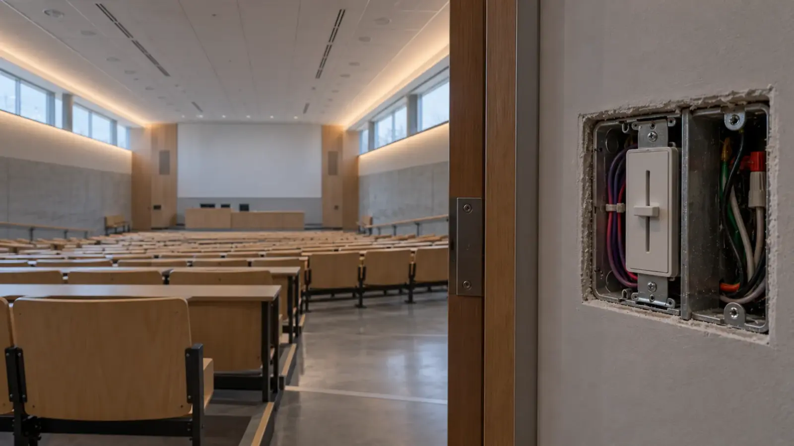
The circuit. In a dwelling unit kitchen the countertop receptacles sit on small-appliance branch circuits. Mike Holt’s Code Q&A for EC&M, based on the 2023 NEC, quotes 210.52(B)(2): “The two or more small-appliance branch circuits specified in 210.52(B)(1) shall have no other outlets.” His Understanding the 2023 NEC reads it as excluding lighting outlets, so a hardwired driver usually goes on a lighting circuit with its own switch. Whether a plug-in kit at a counter receptacle passes is the AHJ’s call; ask before a kit is chosen.
The box and the driver. The line-voltage connection lands in a junction box or the driver’s own wiring compartment, as its listing allows. The driver goes where it can be reached and replaced, never in the toe kick; see our driver location ranking and junction box and splice notes.
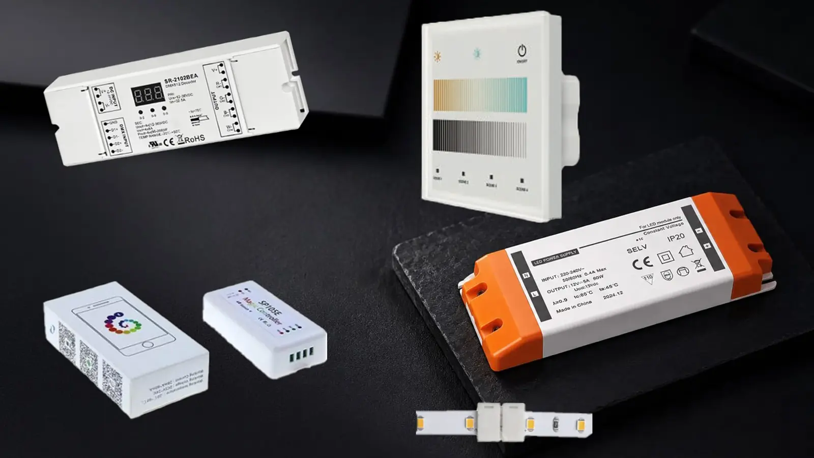
The driver. Two Class 2 LED drivers cover most units: UT-D40-24-C2 at 40 W and UT-D60-24-C2 at 60 W, both IP20 for dry locations. A unit with more than 48 W of strip splits across two.
Dimming. An existing TRIAC dimmer needs a TRIAC driver such as UT-D60-24-TRC, which sits outside our Class 2 group; new 0-10V work takes the Class 2 UT-D60-24-C2-010. Minimum loads are in the dimming section.
Code. How the AHJ counts Class 2 circuits, whether the driver location counts as accessible, and the wiring method for the 24V lead get settled before rough-in; the code notes list them, and our 120V cord rule guide explains why a cord run into a wall fails.
Switches, Sensors and Door Switches
Most unit kitchens switch the driver’s input from a wall switch. Sensors and door switches change that.
A motion sensor or cabinet door switch on the 24V side breaks the strip current, so rate it in amps at 24V, not by a wattage printed for another voltage. The unit above draws 1.5 A; a pantry cabinet with 4 ft of UT-C480-8 draws about 0.5 A. A sensor that switches the driver’s input instead sees the driver’s inrush each time it fires, which our occupancy sensor guide shows can weld relay contacts. In nonresidential spaces such as a hotel pantry or staff break room, the energy code may require automatic shutoff; our Title 24 guide covers the California text.
Toe Kick and Shelf Lighting on the Same System
Run the load before a toe kick joins the same driver. Add an 8 ft toe kick of UT-O320-8-65, the IP65 silicone-coated strip at 2.4 W/ft, to the unit above:
| Option | Under cabinet | Toe kick | Total | On one 60 W driver |
|---|---|---|---|---|
| Same driver, UT-C480-8 above | 36.8 W | 19.2 W | 56.0 W | 93%, over the 80% line |
| Fix 1: second driver for the toe kick | 36.8 W on UT-D60-24-C2 | 19.2 W on UT-D40-24-C2 | 61% and 48% | |
| Fix 2: UT-C320-8 above at 2.4 W/ft | 27.6 W | 19.2 W | 46.8 W | 78% |
Fix 1 costs a second driver per unit and buys separate switching, which a night-path toe kick needs anyway; Fix 2 puts a quarter less power into the counter. We would choose Fix 1.
The toe kick gets mopped, so it takes outdoor-rated IP65 strip with sealed ends, set back from the plinth’s front edge. On glass-front cabinets and open shelves color shows: our application page pairs Ra≥98 SMD with the 45-degree UT-CH1616 corner channel, and pucks are a fair choice there too. Keep under cabinet, shelf and toe kick on one CCT, matched to the downlights; our high-CRI guide covers when Ra≥95 earns its lower efficacy.
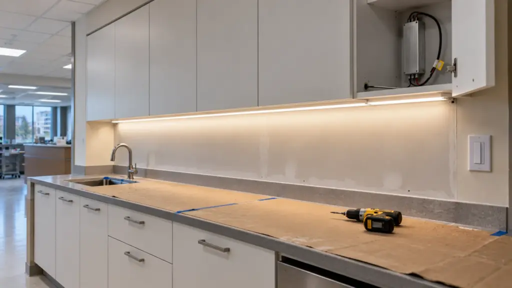
How to Install Under Cabinet LED Strip, Step by Step
The install is short; the coordination around it goes wrong, so each step ends with a check before the next trade moves in.
- At rough-in, put the box and the driver on the drawing. Mark the switch, junction box and driver location for each unit type, and decide who furnishes and who connects the strip; our millwork scope guide sets out the splits. *Check:* the driver is reachable without removing a finished panel.
- Before the cabinets are built, set the feed holes in each cabinet bottom and through the side into the cabinet that holds the driver. *Check:* hole positions are on the shop drawings.
- In the mockup unit, tape the strip in place toward the front edge, behind the light rail, and look from standing height with the countertop in; polished stone shows a reflected line if the strip sits too far forward (placement trade-offs). *Check:* the owner signs off the position.
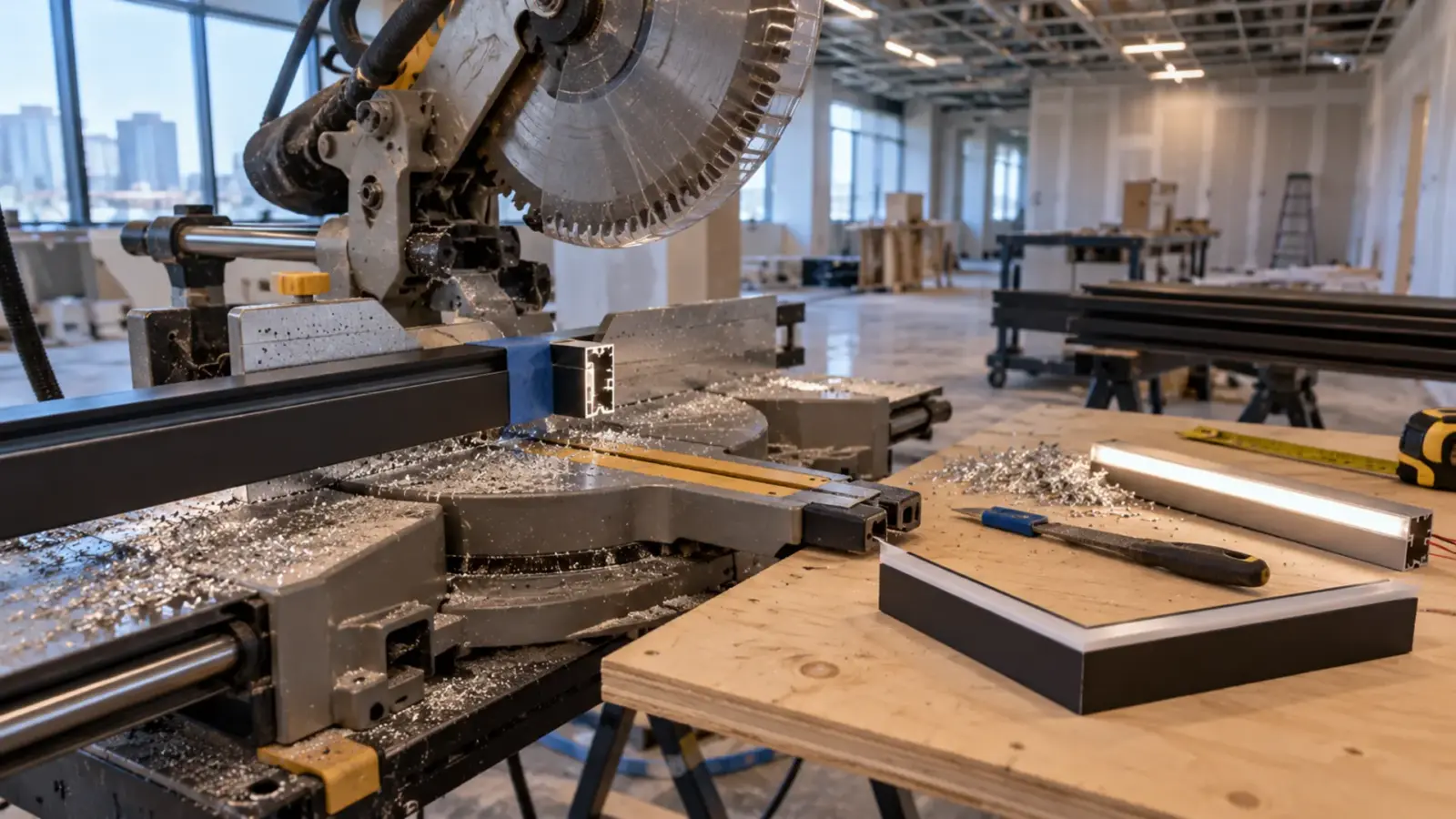
- After the cabinets are hung, before the backsplash, mount the channel. Fix the LED channel with its clips or screws and pull each lead through, with slack at the driver. *Check:* every lead carries its run number at both ends.
- Cut, connect and test each run. Cut only on the marks, check polarity, and light every run from its driver before a cover goes on. *Check:* the far end matches the near end by eye.
- Close it up. Snap in the opal cover, fit the end caps, and screw the driver in place with air around it. *Check:* the driver comes out with a screwdriver.
- Check at the counter at the front edge, the middle and the backsplash line, at both ends of every run, and compare color with the next run. *Check:* a closeout sheet maps each driver to its runs.
FAQ
Do under cabinet LED strip lights need a transformer?
A 24V under cabinet LED strip needs a driver, a constant-voltage power supply that turns 120V AC into 24V DC, often called a transformer. A 120V strip runs from a rectifier plug without one, but its long cut increment suits wall cabinets poorly.
Is 12V or 24V better for under cabinet lighting?
24V suits most jobs. At the same load it draws half the current of 12V, so a remote driver’s lead loses a quarter as large a share of the supply. Keep 12V for short retrofits with the driver beside the strip, and check a longer lead in our voltage drop calculator.
Can plug-in under cabinet lights be hardwired?
Only if the product’s listing and instructions allow it. Some fixtures ship with both a cord and a hardwire option; others say they are not for hardwire use. Cutting the plug off a cord-and-plug product does not make it a hardwired one.
Before You Order
Write one line per unit type: cabinet runs in inches, strip model and CCT, channel and cover, driver model and location, the control, and the lead length. Check the load against 80% of the driver and the cut lengths against the cabinet widths.
Send us the unit-type schedule and the electrical plan. We return strip, channel and driver for each unit type with every cut length worked out, so the cabinet shop and the electrician order from one list: request a quote. The finished detail for kitchens, toe kicks and casework is on our under cabinet lighting page.