To backlight a stretch ceiling without hot spots, set the depth first, make the strip pitch about equal to it, paint the cavity white, test the rows under the real membrane, and leave a way in. More depth means fewer rows and fewer watts.
The membrane goes up on Thursday, and the first test shows a bright bar over every strip row. The fix is rarely more LEDs. It is depth and pitch, in that order, and the arithmetic takes ten minutes. This how-to follows the order of the job, with a check at each step.
What You Need
- The ceiling drawing with the clear depth between the structure and the membrane, in inches and millimeters.
- The membrane’s light transmission, from the supplier.
- Dot-free strip, such as COB strip UT-C480-8 at 3.2 W/ft, in aluminum channels or on an aluminum back plate.
- White paint for the cavity, a bus wire for each branch, and a driver plan.
- A test panel of the same membrane, if the project allows one.
Step 1: Choose the Membrane and the Depth
The membrane decides how much light gets through, and the depth decides how well it blends. According to Lumistrips, a white translucent ceiling should transmit at least 50% of the light, and dark or heavily printed membranes should be avoided because they absorb too much. Ask the supplier for the transmission of the exact sheet and print.
Depth is the larger lever, and the sources disagree on the number, which is why the mock-up decides.
| Source | Depth | What it applies to |
|---|---|---|
| Lumistrips | About 30 to 50 cm (12 to 20 in) between source and membrane | LED modules and strip, general |
| Barrisol | About 150 mm (6 in) for a homogeneous result | Its own system, with the plenum painted white |
| A stretch-ceiling installer’s test | No hot spots at about 152 mm on one translucent panel | A single homemade test, not a standard |
Checkpoint: write down the depth you actually have, to the nearest half inch, at the shallowest point of the ceiling. The shallowest point sets the pitch for the whole ceiling.
Step 2: Set the Pitch From the Depth
According to Lumistrips, for typical 120° LEDs the gap between strip rows should match the distance from the LEDs to the membrane; for 180° LEDs it suggests a ratio of 1.5. Our COB strip reads as a wide-angle line, so use the 120° rule as the starting point, and prove it in Step 5.
Pitch drives the watts. Watts per square foot equal 12 divided by the pitch in inches, times the strip’s W/ft. For a 10 × 12 ft ceiling (120 ft²) on UT-C480-8:
| Depth and pitch | W/ft² | Rows (10 ft wide) | Strip length | Load |
|---|---|---|---|---|
| 6 in, 6 in pitch | 6.4 | 20 | 240 ft | 768 W |
| 12 in, 12 in pitch | 3.2 | 10 | 120 ft | 384 W |
| 20 in, 20 in pitch | 1.9 | 6 | 72 ft | 230 W |
Doubling the depth halves the strip and the load. That is the argument for asking the ceiling designer for the deeper plenum, and it is the one that wins the discussion, because strip, drivers and heat all fall with it. According to Lumistrips, a shallower cavity needs more LEDs, which raises the cost.
When the depth is shallow, there are two honest answers. Tighten the pitch, which adds rows and watts, or use a denser strip such as UT-C960-15 (15 mm PCB, 7.6 W/ft), which gives more overlap from each row. Neither is free: the first adds cost and heat, and the second is a wider, hotter strip that needs its aluminum. The cheapest answer is almost always the deeper plenum, and it is worth a short conversation with the ceiling designer before the order.
Checkpoint: the row count, the strip length and the total watts are on the drawing before the order, and the pitch is not wider than the depth.
Step 3: Build the Plenum
The cavity is part of the light. According to Barrisol, the plenum should be painted white so it reflects light toward the membrane, and a clear sheet between the LEDs and the translucent ceiling keeps dust and insects out of the cavity. Keep the back flat and matte white, run the rows parallel and at the same height, and seal the perimeter so light does not leak around the track.
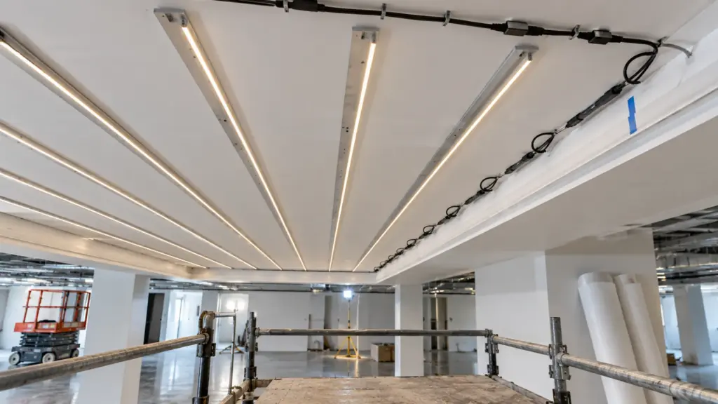
Fix the strip to an aluminum channel or back plate. Higher-watt strip needs the metal behind it, as our thermal management guide explains, and a ceiling plenum is a closed, warm space. Edge rows sit close to the track and look darker or brighter than the field, so set the first and last rows by the mock-up and expect them to differ from the pitch.
Checkpoint: the cavity is painted, the rows are straight and equal in height, and the edge rows are marked separately.
Step 4: Wire and Power
Run each row as its own branch off a bus wire, with a connector at each row so one can be changed. Our rows are 12 ft long in the example, well under the 16 ft per feed on UT-C480-8, so voltage drop does not limit the layout. The driver does. A 384 W ceiling splits across several drivers and branch circuits, as covered in what the inspector checks on a Class 2 driver, and a color difference between runs is avoided by ordering all strip for the ceiling in one run, as in why the second reel does not match.
Put the drivers outside the cavity, in a ceiling void with a hatch or a plant room, with the loop of cable at each branch.
Checkpoint: every branch is labeled, every driver is reachable and the load per driver is written next to it.
Step 5: Test Before the Membrane Goes Up
Light the rows and put the real membrane, or a test panel of it, in place at the real depth. Look at it from the floor at three angles: straight up, across the room at a low angle and along the ceiling from a corner. Look for bright bars over the rows, dark bands between them, brighter edge rows and any dots through the membrane; the fixes for dots are in how to fix dots showing through a diffuser.
| Symptom | Likely cause | Fix |
|---|---|---|
| A bright bar over each row | Pitch wider than depth | Add rows, or get depth |
| Dark bands between rows | Same | Same |
| Bright or dark edge rows | Row close to the track | Move the row, change its output |
| Dots show | Too shallow for the strip | More depth, or a denser strip |
| A yellow or pink patch | A strip from a different run | Replace with matched strip |
Checkpoint: a photograph of the test at full and at the dimmed level, signed off before the membrane is installed.
Edges, Corners and the Track
The perimeter is where stretch ceilings differ from a flat panel. The membrane clips into a track at the wall, and the cavity near the track is shallower than the field. Rows close to the track show as bright bars on the edge, or leave a dark band if they are set too far in. Start the first row at about half the pitch from the track, then adjust in the mock-up. At an inside corner, add a short row across the end so the corner does not go dark, and keep strip ends away from the track by an inch or more so the end cap does not print through the membrane.
Where the ceiling has a step or a curve, the depth changes. Use the shallowest depth in the area to set the pitch for that area, and treat each depth zone as its own set of rows on its own branch.
Plan Access
A stretch ceiling comes down at the perimeter, and the installer decides how. Ask the membrane installer how the sheet is released, whether a section can be removed without pulling the whole ceiling, and where a hatch can go. Mark a service hatch, or a removable panel, on the drawing near each driver and each cluster of rows. A cavity that can be reached only through the membrane is serviced only once. Label each hatch on the drawing with the rows and the driver it serves, and leave a clear path above the ceiling so the person who comes to fix a row can reach it with a ladder and a torch, not a saw.
Mistakes That Show After the Membrane Is Up
Four mistakes cause most of the call-backs on a backlit ceiling.
- Pitch wider than depth. The rows show as bars. The only cure after the membrane is up is to take it down.
- Strip stuck to the structure with no metal behind it. The strip runs hot in a closed plenum, loses output and shifts color over time.
- Strip from two production runs in one ceiling. A patch of a different white shows when the ceiling is lit and the room is dark.
- No access. The first failed row means cutting the ceiling, and the owner pays for the membrane twice.
Dimming makes the first and the last worse. Check the evenness at the lowest level the room will use as well as at full output, because a ceiling that looks even at 100% can show bars at 10%.
Final Checks
Before the order is released, confirm six items on the drawing: the shallowest depth, the pitch against the depth, the rows and the total watts, the white cavity, the driver locations with a hatch, and the mock-up photo. Our backlit panel guide covers the same depth-and-pitch logic for stone and acrylic faces.