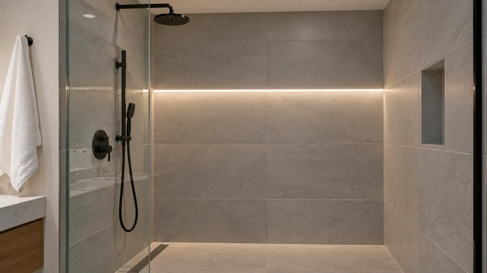


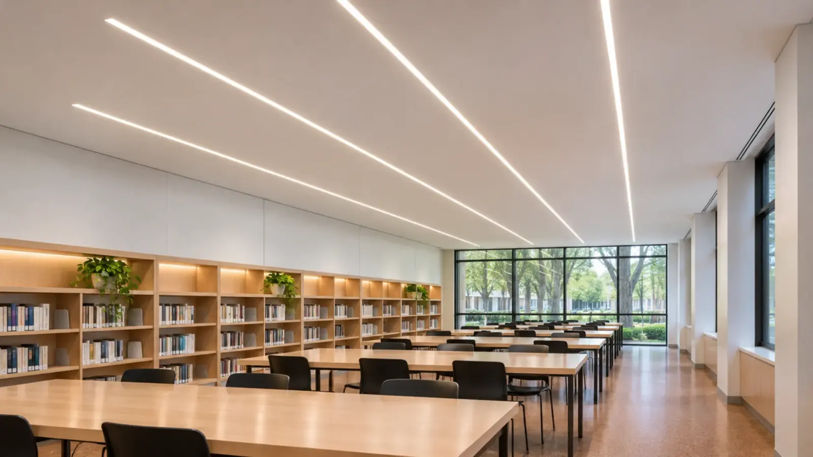
Linear lighting is light delivered as a continuous line instead of as points: a slot in the ceiling, a bar hung over a desk, a run along a shelf, or a glow out of a Strip hidden on a ledge or in a recess that lights the ceiling indirectly. The cove's depth and lip height decide the throw and whether the strip is seen.. The word names the shape of the light, not a product, so one line on a drawing can be built two ways.
On a reflected ceiling plan that line can arrive as a listed linear fixture or as LED strip in an aluminum channel, and those two are bought, submitted and inspected differently. So “what is linear lighting” has two answers on a job: the mounting (recessed, suspended, surface or cove) and the build. This article sorts both and works one run through to the joints and A place where driver cable lands on the strip. The model's run limit per feed sets how many a run needs..
Linear Lighting Defined: A Shape, Not a Product
A linear light is long and narrow, and the eye reads it as one line. It can be direct, where you see the lit face, or indirect, where the source is hidden and you see the light it puts on a ceiling or a wall.
Most lines on a commercial drawing fall into four mountings:
- Recessed: set into the ceiling, wall or millwork so the lit face sits flush.
- Suspended: hung from the structure on cables, so the line sits in the room.
- Surface: fixed to a finished surface, so the body of the line is visible.
- Cove: hidden behind a lip or in a ledge, so only the light shows.
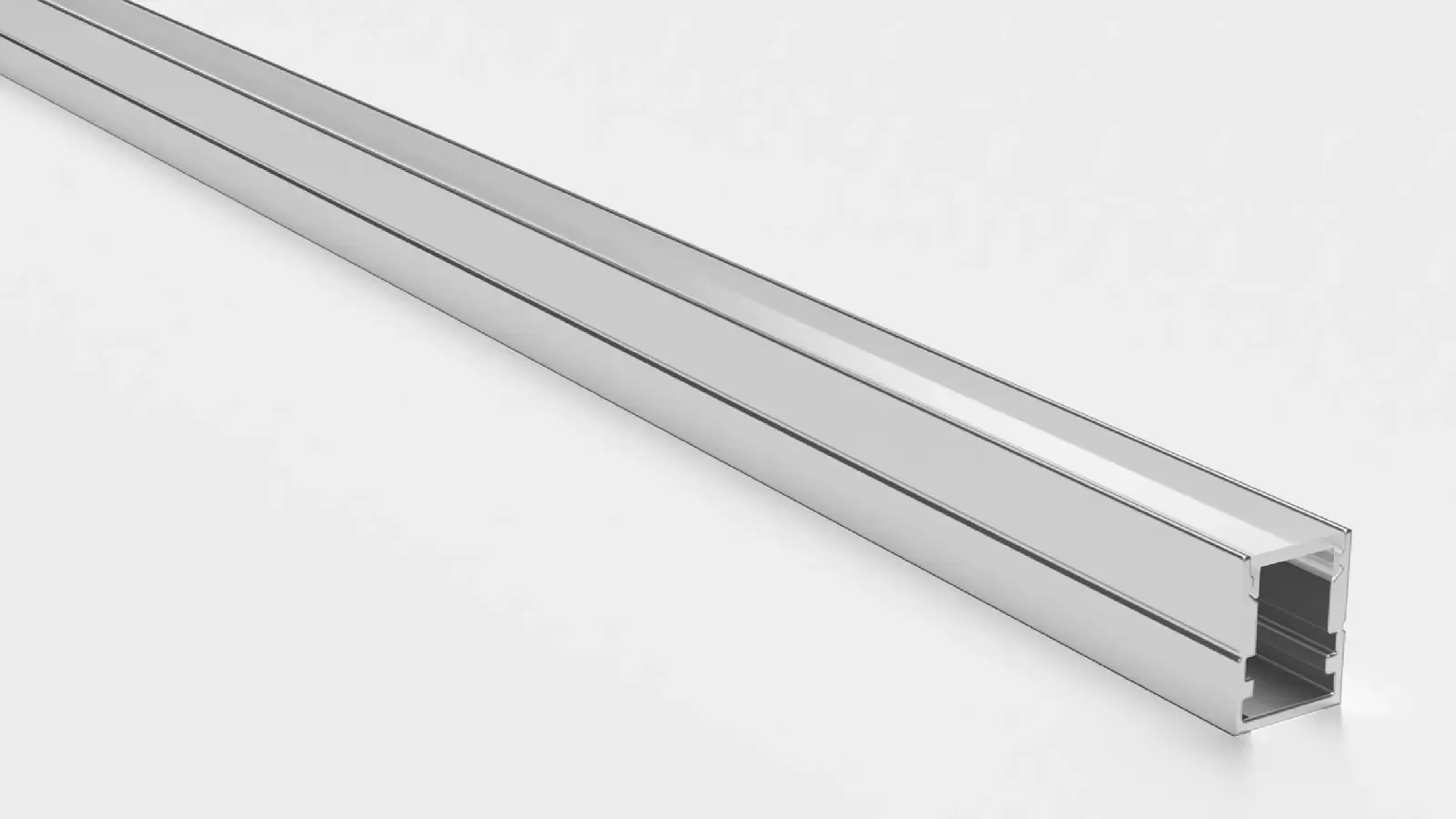
Each of the four can be built two ways. A linear fixture is a factory-made luminaire with its own housing, optics and connection. A strip system is LED strip in an aluminum channel behind a The cover on a channel that softens the LED points: clear keeps output, frosted blurs, opal hides the dots at the cost of some light., assembled on site or in a shop from parts that each carry their own data. A cove can also be lit with bare strip and no channel at all.
Recessed Linear: A Slot in the Ceiling
Recessed linear is the line that looks drawn into the ceiling. In drywall it is usually a trimless, plaster-in profile: our UT-CH2020 is 20.2×19.5 mm (0.80×0.77 in) with mounting wings that take joint compound, so only the lit line shows after paint. In millwork or a reveal it is a flanged profile such as UT-CH1708 (17×8 mm) or UT-CH1715 (17×15 mm).
What it needs is an open ceiling. The channel and its wire are fixed to blocking before the board goes up, the finisher tapes the flanges, and the strip and cover go in after paint. A concrete deck with no cavity, or a ceiling that is already closed, pushes the line to surface or suspended mounting. Our guide to recessed linear LED in offices covers the grid and drywall conflicts in detail.
Suspended Linear: A Line Hung in the Room
A suspended line hangs below the ceiling, usually over desks, counters or a reception area, and it is seen from below and from the side. Built as a strip system it is a surface or wide-body profile on aircraft cable: UT-CH3020 (30×20 mm, 20 mm strip) carries wide or doubled strip, and UT-CH2415 (24×15 mm) gives depth for a dot-free line.
The building has to give it support. The cables go to structure or to reinforced grid, not to an unreinforced tile, the driver sits above the ceiling, and the feed comes down through the canopy at the feed end. The line has to be level before the cover is trimmed, because a sag shows from across the room. Our note on hanging a linear LED channel works through the hang points and the feed.
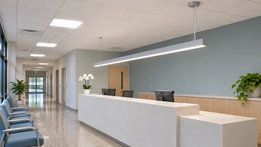
Surface Linear: When There Is No Cavity
Surface linear is fixed straight to a finished surface: the underside of a cabinet, a shelf edge, a stair stringer, a concrete soffit. Nothing is cut into the substrate, which makes it the retrofit choice and the answer when the ceiling has no depth.
The cost is that the body is visible, so the profile becomes part of the design. UT-CH1013 is 10 mm tall for under-cabinet work and UT-CH1207 tucks into shelf reveals, while UT-CH2415’s depth (about 14.5 mm of optical depth) blends denser strip into one line where the run is seen head-on. The things to plan are the fixings, the end caps and where the lead leaves the run.
Cove: Linear Light You Do Not See
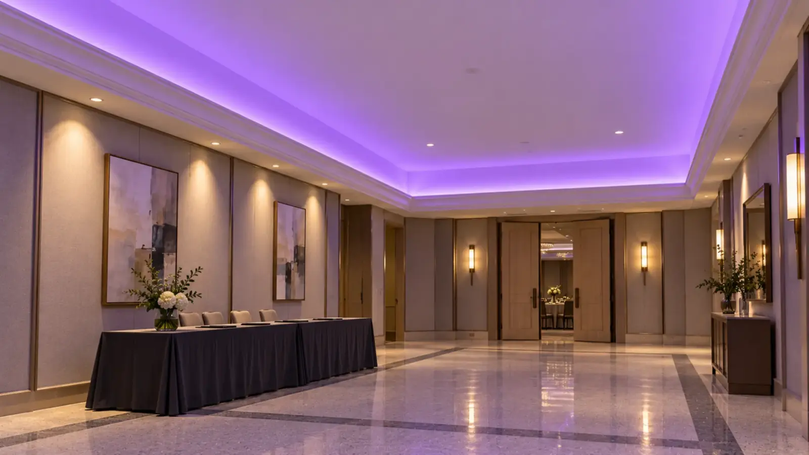
A cove is linear lighting with the source hidden. The strip sits on the cove floor or ledge, behind a lip, and lights the ceiling or the wall above it, so the room sees a soft gradient instead of a line. It is the indirect member of the family, and the one most often built from strip instead of a fixture.
Because nobody looks at the source, a deep cove can take bare strip, provided the strip’s instructions allow its mounting surface. Where the light has to be aimed out of a shallow ledge, a 45° corner profile such as UT-CH1616 (16×16 mm) turns it toward the ceiling. The choice of strip for the gradient is its own question; our COB vs SMD cove guide goes through it.
Four Mountings Side by Side
| Mounting | What the building must provide | How the line reads | Strip-in-channel version | Settle before the ceiling closes |
|---|---|---|---|---|
| Recessed | An open ceiling or millwork with room for the profile (UT-CH2020 is 19.5 mm tall) plus the wire | A flush lit line, the source seen directly | UT-CH2020 trimless plaster-in; UT-CH1708 / UT-CH1715 flanged | Blocking, the channel and the wire in place before the board goes up |
| Suspended | Structure or reinforced grid for every hang point | A line in the room, seen from below and the side | UT-CH3020 or UT-CH2415 on aircraft cable | Hang points, the canopy feed, a reachable driver above the ceiling |
| Surface | A flat, sound finished surface | A visible body with a lit face | UT-CH1013, UT-CH1207, UT-CH2415 | Lead exits and the driver location |
| Cove | A cove or ledge with a lip above the sightline | Light on the ceiling or wall, source hidden | Bare strip, or UT-CH1616 aimed out | Cove depth, a feed point inside the cove, access to the driver |
All of our channels come in 2 m or 3 m (6.6 or 9.8 ft) lengths with clear and opal covers, so the length of a line decides its joints whatever the mounting. The LED channels and diffusers page lists each profile’s dimensions and maximum strip width.
Where LED Strip Fits: Fixture or Components
A linear fixture and a strip system can light the same slot, and an inspector and a lighting designer still treat them as different submittals.
| Linear fixture | Strip in a channel | |
|---|---|---|
| What arrives | One luminaire in factory lengths, with its own joiners and connection | Strip, channel, cover, end caps, clips and driver, each with its own data |
| Listing paper | Usually its own listing as a luminaire (the UL 1598 case) | A strip sold as a low-voltage system is normally listed to UL 2108; the driver has its own paper |
| Photometric file | Usually one IES file for the fixture | Depends on the exact strip, channel and cover combination |
| Lengths and joints | Set by the fixture’s sections | Set by the channel pieces and the strip’s cut points |
| Who answers for the assembly | The fixture maker | The installer, from the parts’ data |
The strip system wins where the line has to follow the building: odd lengths, a groove in drywall, a cove, millwork, a run cut to a schedule. The fixture wins where the specification names a listed luminaire and a photometric file and nobody wants to rebuild that paper. Which listing applies to which product is set out in our guide to UL 2108, UL 8750 and UL 1598, and the photometric side in which IES file a strip in a channel needs. If a strip system is offered in place of a specified fixture, six things move to the installer; our guide to replacing a linear fixture with strip in a channel goes through each.
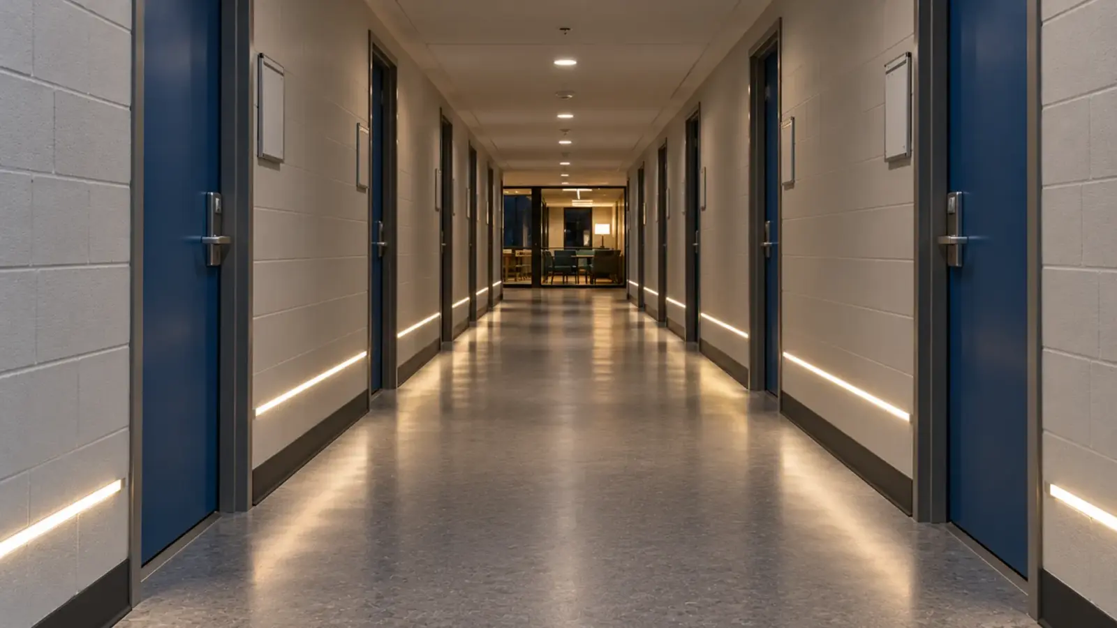
A Worked Line: 40 ft Down a Corridor
Take one typical case: a recessed line 40 ft (12.2 m) long down a school or clinic corridor, built as a strip system in UT-CH2020 with dot-free COB LED strip. UT-C480-8 has an 8 mm PCB, inside the channel’s 12 mm maximum.
Channel pieces. In 3 m (9.8 ft) lengths, 40 ft takes five pieces, one of them cut, so four joints. In 2 m (6.6 ft) lengths it takes seven pieces and six joints. Put the joints on the run schedule so they land where the drywall and the ceiling grid allow.
Feeds and load. The strip decides the feeds, not the channel:
| Strip | Power | Run per feed | Feeds for 40 ft | Load | Drivers, loaded to 80% or less |
|---|---|---|---|---|---|
| UT-C480-8, 24V | 3.2 W/ft (10.5 W/m) | 16 ft (5 m) | 3 | 128 W, about 43 W per feed | Three 60 W Class 2 drivers, one per feed (48 W is 80% of 60 W) |
| UT-C480-8-48V, 48V | 2.4 W/ft (8 W/m) | 65 ft (20 m) single feed | 1 | about 98 W | One 48V driver of at least 125 W, which is not a Class 2 supply |
At 24V the line needs three feed points in the ceiling and three drivers, each with a wire route and an access point, all decided before the board goes up. At 48V the same line runs from one end on one larger driver, and that driver is not a Class 2 supply; our Class 2 driver guide covers what that changes for the wiring and the inspector. That difference matters more to a closed ceiling than anything in the channel. A fixture line would answer the same questions from the fixture maker’s section lengths and feed instructions instead.
The Short Version
Linear lighting is a line of light, and a drawing that says “linear” leaves two decisions open: the mounting (recessed, suspended, surface or cove) and the build (a listed fixture or strip in a channel). Settle both before rough-in, because each mounting needs something from the building and each build brings different paper. Then count the joints from the channel lengths and the feeds from the strip, not the other way round.
The profiles named here are in our LED channels and diffusers range, and on larger jobs we pre-cut channels to the run schedule and send CAD sections with the quote.