PET felt is not the fire problem people expect. It is an insulator, and that is the problem for a strip buried in it. Acoustic baffle LED lighting integration works when the strip sits in an aluminum channel on the baffle’s edge, in air, with the felt’s ASTM E84 class on the submittal and plenum-rated cable up the hanger.
The questions below come up on a felt ceiling job in this order, from “can we?” to “who pulls the baffle down?”.
Can Strip Go Inside a Felt Baffle?
Yes, and manufacturers already sell it that way. One European felt-baffle maker’s clip-in luminaire takes two 1 m lamps per 2.4 m baffle, each lens 40 mm wide, in a baffle at least 102 mm wide. US felt-baffle makers offer lit baffles with diffused channels embedded in the felt, and a USG Interiors patent for metal baffles describes an integrated strip behind perforated walls. The precedent is settled; the engineering is not automatic.
Three things decide whether a job’s version works: where the strip’s heat goes, what the felt’s fire rating covers, and who owns the wiring and the access. Each has a cheap answer at the design stage and an expensive one after the ceiling is hung.
Where the Heat Goes
A strip in a channel on a ceiling or in a cove sheds heat into the metal and from the metal into open air. A strip inside a felt baffle sheds heat into a material whose whole purpose is to trap air. Felt is a good acoustic absorber for the same reason it is a poor heat sink.
The USG patent states the problem in its own terms: “heat build-up in the baffle space detrimental to the light elements can be reduced by air currents passing through the baffle wall perforations”. Our channel thermal guide explains why there is no per-millimeter rule for a channel; the rule is a path to air. For a baffle that means the channel is mounted on the bottom edge or in a slot that opens to the room, with its aluminum body exposed on at least one face, never wrapped in felt on all sides.
| 8 ft (2.4 m) baffle, one run | Strip | Load per baffle | Channel | Heat path |
|---|---|---|---|---|
| Low output, continuous line | UT-S2835-60 SMD, 1.5 W/ft (4.8 W/m) | 12 W | UT-CH1207, 12×7 mm, opal | Channel on the bottom edge, body in air |
| Standard dot-free line | UT-C320-8 COB, 2.4 W/ft (8 W/m) | 19 W | UT-CH1013, 13×10 mm, opal | Same; felt kept off the channel sides |
| High efficacy, more light per watt | UT-S2835-128-HE, 2.9 W/ft (9.6 W/m) | 23 W | UT-CH1013 or UT-CH1708 recessed | Recessed flange leaves the cover face open |
| Brighter dot-free | UT-C480-8 COB, 3.2 W/ft (10.5 W/m) | 26 W | UT-CH2415, 24×15 mm deep | Deep channel, body exposed on the edge |
The loads are small; a baffle is not a cove. The point of the table is the last column. A 12 W strip in a channel open to air runs cool for its rated life; the same 12 W glued into a felt slot with felt on three sides does not, and our strip heat guide sets out what trapped heat does to lifespan.
Two more rules. Keep the strip’s density modest; high-density series are channel-only products and belong in coves, not baffles. And treat the baffle’s own ventilation as part of the design: perforated or slotted baffles move air past the channel, solid felt does not.
What Class A Covers, and What It Does Not
Every PET felt datasheet leads with its fire rating, and most say ASTM E84 Class A. Under the International Building Code’s interior finish classes (803.1.1 in the 2015 edition, 803.1.2 in 2018 and 2021), Class A means a flame spread index of 0 to 25 and a smoke developed index of 0 to 450 in the ASTM E84 (or UL 723) tunnel test; Class B is 26 to 75 and Class C 76 to 200. The felt makers’ numbers vary inside that band: one lists a flame spread index of 0 and smoke developed of 35, another 10 and 250, and one notes its Class A is “based on 9mm white”, that is, one thickness and one color.
Read that for what it is. Class A is a surface burning characteristic of the felt as tested; most rooms need only Class B or C under IBC Table 803.13 (Class A is required in interior exit stairways and some corridors), yet Class A is what the ceiling spec and the fire marshal usually ask for. It is not a heat rating, it says nothing about a heat source inside the panel, and it does not make the lit baffle a listed luminaire. On the submittal, give three documents: the felt’s E84 report for the thickness and color used, the driver’s UL listing and the strip’s listing where a UL Listed strip option is specified, and the baffle maker’s statement of whether its lit assembly carries a luminaire listing. Where none of the three covers the combination, say so before the AHJ asks.
The service temperature is the gap. Industrial PET needlefelt datasheets rate the fiber at 135 °C (275 °F) continuous, but acoustic felt makers publish no service temperature at all. Ask in writing, and design so the question never matters: a channel in air, modest load, no felt pressed against the strip.
In the Baffle or Between the Baffles
There are three places to put the light, and they are not equal.
| Position | What it lights | Spill and glare | Access | Heat path |
|---|---|---|---|---|
| Channel recessed in the baffle’s bottom edge | The floor below, a direct line per baffle | Clean; the baffle shields the source from the side | Pull the baffle down or unclip the channel | Good, body in air |
| Strip on the baffle face, aimed across | The neighboring baffle’s face | Lights the side of the next baffle; the effect the Construction Specifier article warns of | Same | Fair |
| Separate linear rail between baffles | Direct and indirect, independent of the felt | Depends on the rail’s optics; can spill onto baffle faces | Separate fixture, easy | Best, nothing touches felt |
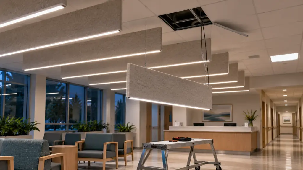
Construction Specifier’s Star Davis describes the usual sequence and its cost: the interior architect sets the baffle layout, the lighting designer fits fixtures into the gaps, and the result “can be visually disruptive, both by forcing the luminaire to fit within the preset baffle spacing” and “potentially projecting light onto the side of some baffles”. Her fix is the order of decisions: “the baffle ceiling can be specified and iterated on, then the lighting designer can choose which baffles to light up”. For strip that means lighting the baffle’s own edge, so the light belongs to the baffle and not to the gap.
Lit edges also give back what baffles take away: the ambient light a ceiling plane would have reflected. That is why an office or a library is the right place for this detail and a corridor usually is not.
Who Owns the Wire, the Driver and the Access
A lit baffle hangs on cables in a return-air plenum, and the strip’s leads have to get from the channel to a driver. The route is up a hanger or a dedicated cord to a junction box above, and the cable in the plenum has to be rated for it; our in-wall and plenum cable guide covers CL2P and the Class 2 separation rules. The driver does not ride in the baffle. It goes above the ceiling where it can be reached, or in a closet, per our remote driver guide, and the plenum temperature in summer decides its derating, as our hot ceiling guide explains. One 60 W Class 2 driver at 80 percent carries four 12 W baffles, each on its own lead, with the feed lengths checked against the voltage drop.
Access is the question nobody asks until the first failure. The USG patent’s answer is mechanical: torsion springs that let the baffle “be manually pulled down for access to the plenum space”. Whatever the baffle maker offers, the spec needs one of three: a baffle that drops on its hangers, a channel that unclips from the baffle’s edge with a plug connector at the lead, or a rail between baffles that is its own fixture. A strip glued into a felt slot with a soldered lead is a baffle that gets thrown away.
Then the trade split. Davis recommends specifying the ceiling under “Division 09 for ceiling products and Division 26 for lighting products” with cross-references in each, so the ceiling contractor hangs the baffle and the electrical contractor owns the strip, the driver and the connection, and both bid on what they can see.
Strip, Channel and Driver for a Lit Baffle
Pick the strip for a line that will be looked at from 8 ft below and across a room: Ra≥90, a single color temperature across every baffle, 4000K in offices, classrooms and libraries, and a modest output. The low-density 2835 strip, UT-S2835-60 at 1.5 W/ft, gives a soft line behind an opal cover; the high-efficacy UT-S2835-128-HE at 2.9 W/ft and 190 lm/W gives more light per watt of heat where the room needs the baffles to carry real illuminance. Our SMD LED strip page lists both; a dot-free COB such as UT-C320-8 is the choice when the cover is clear or shallow.
The channel is the heat sink and the mounting. A surface profile such as UT-CH1207 (12×7 mm) or UT-CH1013 (13×10 mm) screws to the baffle’s bottom edge with its aluminum body exposed; the recessed UT-CH1708 (17×8 mm) sits in a routed slot with its flange on the felt face and its cover open to the room, which is the neatest detail when the baffle is thick enough. Opal covers hide the diodes at 8 ft; clear covers do not. The LED channel range lists the maximum strip width for each.
Drivers follow the rules above: Class 2, 60 W rated, loaded to 80 percent, in a reachable place above the ceiling or in a closet, one lead per baffle with a plug connector at the channel. Where the room dims for presentations, the 0-10V UT-D60-24-C2-010 ties the baffles to the same control as the rest of the ceiling.
Coordination: One Set of Drawings
Everything above fails if the baffle layout moves after the lighting is drawn. Davis’s example is the ordinary one: a decision that the baffles need “457.2 mm (18 in.) of on-center spacing… instead of 304.8 mm (12 in.)” sends every luminaire back to the drawing. The Unidus integration guide puts the rule plainly: “Acoustic teams, electrical contractors, and MEP engineers must work from one unified set of drawings”, and “Changes to the ceiling layout after services coordination is complete are expensive”. Put the lit baffles, hanger points, junction boxes and driver locations on one reflected ceiling plan, and let the acoustician confirm the baffle count on that plan; a channel on a few baffle edges removes little absorptive area, which the acoustician confirms, but a changed spacing changes everything else.
The Short Version
- Strip goes in an aluminum channel on the baffle’s bottom edge with the body in air; never buried in felt.
- Keep the load modest, about 12 to 26 W per 8 ft baffle, and favor ventilated baffles.
- Class A under ASTM E84 is a surface burning rating for the felt as tested, not a heat rating and not a luminaire listing; submit the E84 report, the driver’s UL listing (and the strip’s where a UL Listed option is specified), and the baffle maker’s statement.
- Light the baffle’s edge, not the next baffle’s face; decide the baffle layout first, then which baffles light up.
- Plenum-rated cable up the hanger, driver reachable above the ceiling, a plug connector at every channel, and a baffle that drops or a channel that unclips.
- Division 09 hangs the baffle, Division 26 owns the strip; one reflected ceiling plan for both.
The low-output SMD strip and the channels in the tables are in our SMD and LED channel ranges; send the baffle section and the ceiling plan with your quote request and we will mark the channel, the load per baffle and the driver count.