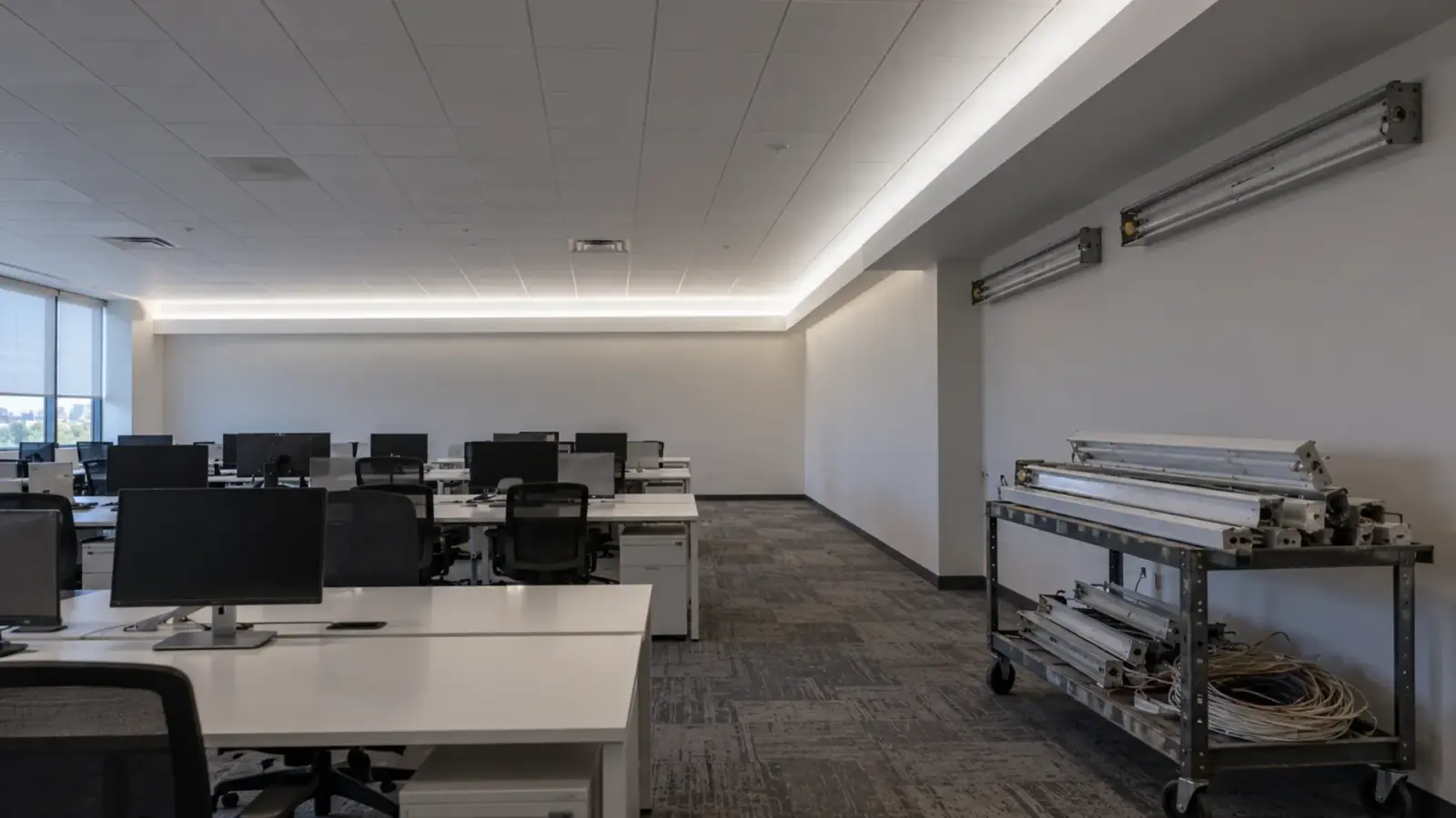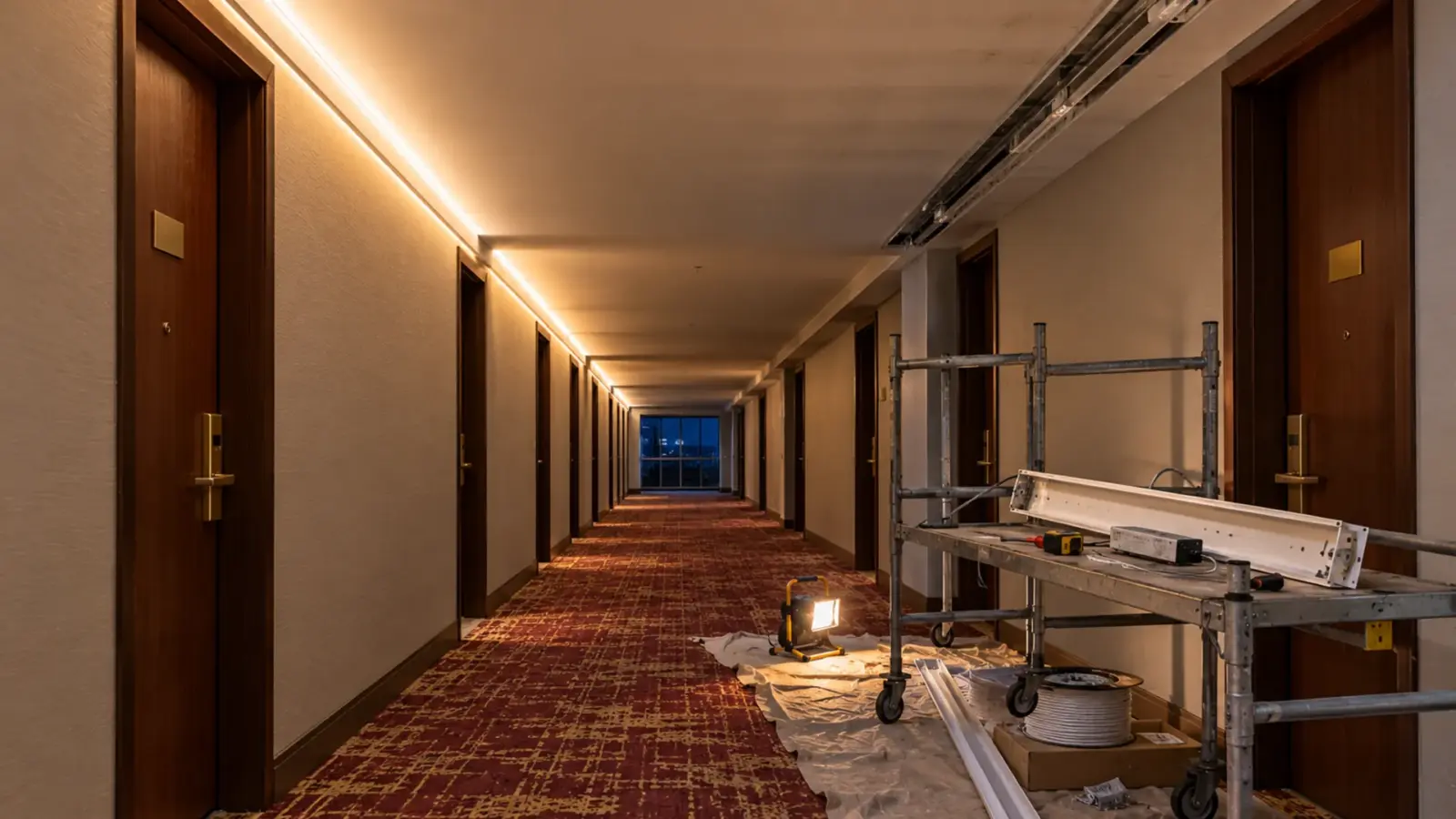
A fluorescent cove upgrade looks like a lamp swap: pull the T8s, push in LED tubes, done. The ceiling says otherwise. Replacing fluorescent cove lighting with LED strip works as a new source in an old trough, one floor at a time: decide whether the 120V circuit stays, match the output on a mockup, settle the dimming, repeat.
The sequence below is written for the building that cannot close: a hotel corridor, a hospital floor, a school that empties at 4 p.m. Each step ends with a checkpoint the next floor depends on.
What the Old Cove Got Wrong
Before choosing the new source, look at why the old one was never right. A T8 cove is a row of 4 ft strip fixtures laid end to end, and every fixture has two sockets. The background of a US patent application for a shadow-free cove light says it plainly: the sockets “form a non-luminous feature at each end of the light fixture”, and fixtures placed end to end leave “a gap in the illumination field”. Architect magazine’s cove guide gives the designer’s workaround: “Any joints or gaps between fixtures will show up in the light pattern. Socket shadows (dark spots at the end of a lamp) can be eliminated by placing fixtures end-to-end, in a staggered or a slanted arrangement.”
Most existing coves were not staggered. They show a scallop every 4 ft, a color step wherever a lamp was replaced from a different case, and a dark last 2 ft where the run length did not divide by four. A Mike Holt forum poster described the inheritance exactly: a customer “with 13 ft. of cove with a real mishmash of T8 fixtures”. A continuous strip removes all three faults at once, which is the real reason to retrofit; the energy saving comes along for free.
Tubes or Strip: Decide by the Ceiling
The quick fix is a ballast-bypass LED tube in the existing fixture. It keeps the sockets, the fixture spacing and the socket shadows, and it changes the light distribution: a tube aims most of its output in one direction, where a fluorescent lamp radiated all around and the cove reflector was shaped for that. The US Department of Energy’s CALiPER work on LED replacements in existing fixtures, as summarized by its program manager Jim Brodrick, found that “replacement tubes and non-tube retrofit kits – don’t perform as well” as purpose-built LED fixtures because “the existing housings were designed for omnidirectional fluorescents rather than for directional LEDs”. Those tests were on troffers; a cove reflector behaves the same way.
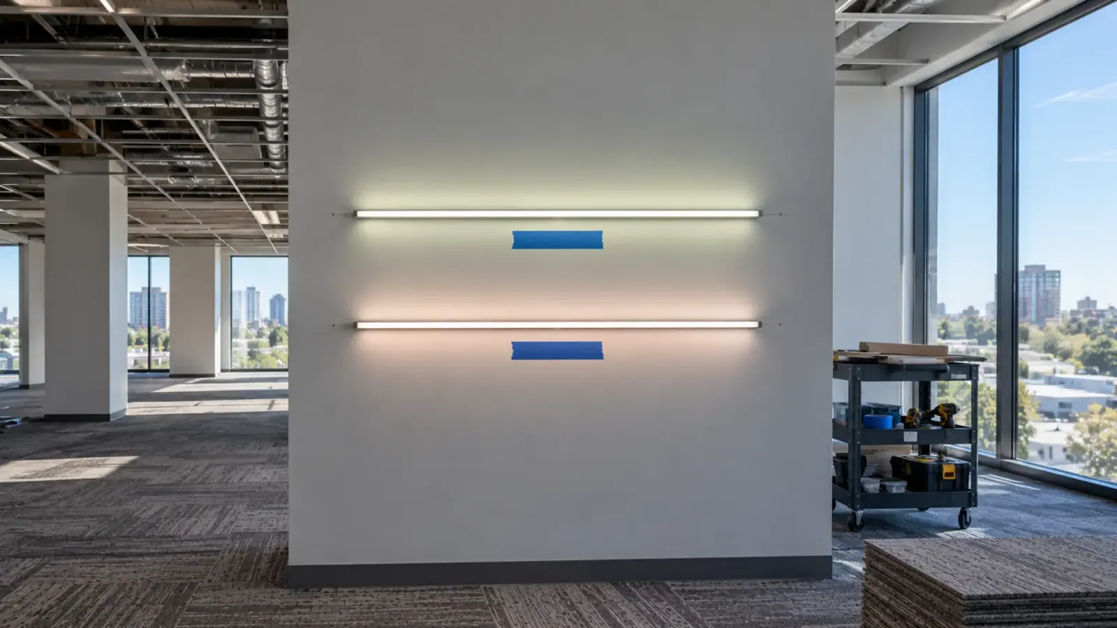
So decide by the ceiling. If the cove is deep, the ceiling far, and the scallops were never visible, bypass tubes are a defensible maintenance fix. If the cove is seen as a line on the ceiling, which is why it was built, the strip wins: it is continuous, it aims where the channel points, and it has no sockets. Brodrick’s other finding applies to both paths: “it’s advisable to mock up and visually evaluate LED retrofit products before ordering them”. One floor’s worth of cove is the mockup.
Keep the Circuit or Add a Driver
The old cove is fed by a 120V lighting circuit, switched or on a relay, with a conductor landing in every fixture. The retrofit either keeps that circuit as the strip’s supply or turns it into a feed for drivers. Both are legitimate; they buy different things.
| Option | Supply | Run per feed | Color quality | Dimming | What it costs you |
|---|---|---|---|---|---|
| Keep the T8 fixture, bypass tube | Existing 120V, ballast removed | Per fixture | Varies by tube | Varies | Socket shadows stay; distribution changes |
| 120V LED strip, UT-H120-120 | Existing 120V circuit, no driver | 98 ft (30 m) single feed | Ra≥80, 2700–6500K | Compatible phase-cut dimmer, confirmed per model | Ra 80 class; cut only every 19.7 in (500 mm) |
| 120V COB strip, UT-H120-296-COB | Existing 120V circuit, no driver | 98 ft (30 m) | Ra≥80, 3000/4000/6000K | Confirmed per model | Dot-free line; 4.9 in (125 mm) cuts |
| 24V constant-current COB, UT-C480-8-CC | 120V circuit feeds a CC driver | 65 ft (20 m) | Ra≥90, 2700–6500K | 0-10V or other, dims below 1% | A driver location per 65 ft and the CC driver pairing |
| 48V COB, UT-C480-8-48V | 120V circuit feeds a 48V driver | 65 ft (20 m) single feed | Ra≥90 | Per driver | 48V drivers supplied on request |
The 120V path is the one a phased retrofit likes. The existing circuit stays live, the ballast comes out, the fixture body comes out, and a strip in a surface channel takes the same feed, wired with line-voltage methods rather than Class 2 rules, as the 120V LED strip page says; the method for the install is confirmed with the AHJ. It is also the path with the trade: Ra≥80 and a 19.7 in cut interval on the SMD version, so a run ends on a half-meter boundary, not where the wall does. Our 120V vs 24V guide sets out when that trade is acceptable.
The low-voltage path keeps the Ra≥90 of our dot-free COB LED strip and the fine cut interval, at the cost of a driver every 65 ft on the constant-current series, which needs a constant-current driver as our CC versus CV guide explains. In a corridor the drivers go above an accessible ceiling tile or in the electrical closet, fed from the same 120V circuit that fed the fixtures; Brodrick’s wiring note applies, “there wasn’t enough wire in some troffers to reach across the fixture once the ballast was cut out”, so plan the junction box and the feed length before the first fixture comes down.
Matching the Output
The number everyone asks for is lumens, and the old number is on the lamp. A 32 W T8 lamp is rated by its maker at roughly 2,850 to 2,950 initial lumens on the Philips ALTO sheets, measured after 100 hours on a reference ballast and multiplied by the ballast factor on the ballast label; a Mike Holt poster’s round figure is “about 2950 lumens”. Per foot of 4 ft fixture that is about 700 to 740 lm/ft of lamp output, before the reflector, the socket gaps and the lamp’s age take their share.
Do not match that number on paper. The cove delivers a fraction of what the source emits, and the fraction depends on the cove’s geometry and finish; our lumens per foot guide works it back from the ceiling target. A high-efficacy 2835 strip such as UT-S2835-128-HE at 2.9 W/ft and 190 lm/W puts out on the order of 550 lm/ft (the two page figures multiplied, rounded down); the CSP UT-CSP-320-N lists 296–316 lm/ft at 3.05 W/ft. The first floor’s mockup is where the meter decides which one the ceiling needs, read on the ceiling at the same points the old cove was judged.
A typical job gives the scale. A 120 ft (36.6 m) hotel corridor cove with thirty single-lamp 4 ft T8 fixtures draws 960 W in lamp watts alone, ballast losses on top. The same cove on UT-H120-120 at 4.3 W/ft draws 516 W on two feeds and keeps the 120V circuit; on UT-C480-8-CC at 2.3 W/ft it draws 276 W on two 65 ft feeds and two drivers. Whether the saving qualifies for a utility rebate is a separate question our DLC and rebates guide answers.
Dimming and the Existing Switch
The old cove was switched, or dimmed on a fluorescent dimming ballast with its own control. Neither carries over. Brodrick’s finding is the warning: “About a third of the LED products exhibited annoying flicker in dimmed mode.” On the 120V path the strip needs a compatible phase-cut dimmer, confirmed per model; on the low-voltage path the driver’s dimming input (0-10V on our UT-D60-24-C2-010 class of drivers) has to match the control the building has or will get. Our driver and dimmer test is a bench procedure for the first floor; run it with the actual dimmer before the order for the other floors is placed.
Energy codes may also want a say. A lighting alteration can trigger the adopted energy code’s control requirements, so a corridor that was switched may come back with occupancy or scheduled dimming; check the adopted code before the controls scope is written.
One Floor a Night: Steps With Checkpoints
- Survey one fixture. Open it, photograph the lamp and ballast labels, measure the cove: lip height, depth, distance to the ceiling, run lengths and where they end. Checkpoint: the survey sheet matches the drawings or corrects them.
- Mock up one run. Install the candidate strip in its channel on one 16 ft length of the first floor’s cove, at the position the diagram shows, and read the ceiling with a meter in the evening. Checkpoint: the owner signs the mockup photo and the meter readings.
- Decide the supply path. 120V strip on the existing circuit, or drivers; confirm the wiring method with the AHJ and the dimmer pairing on the bench. Checkpoint: a one-line sketch per floor with feed points and driver locations.
- Order one floor plus spares, from one production lot, with the cut list taken from the survey. Checkpoint: the delivery is checked against the lot and the color on arrival.
- Install at night, one floor. Demolish fixtures, pull ballasts, set channels, land feeds, cap and test, before the first guest or patient walks the corridor. Checkpoint: every run lit, meter readings at the mockup points, no flicker on the dimmer at its low end.
- Record and repeat. Enter the runs in the maintenance register with lot numbers, as our maintenance plan lays out; order the next floor from the same lot where possible. Checkpoint: the next floor’s order references the first floor’s lot and readings.
The Mike Holt threads hold the cautionary tale for step 2. One electrical contractor reported that LED tubes built from “traditional LED modules” had “proven to be dismal failures… They have failed within a few months”, while tubes using SMD modules on “a flexible, waterproof strip” had been “in service for 9+ months… no element failures”. The mockup floor is where a product proves it survives a hot, dusty trough.
Color Match Across Floors
A phased retrofit creates its own fault: floor 3 done in March from one lot, floor 7 done in June from another. In a cove the sources sit a few inches from the surface they light and small color differences read as a visible step. The defense is lot discipline: order the whole building’s strip from one lot when the schedule allows, hold the spares from the same lot, and record the lot on every floor’s register. Our color consistency guide explains binning and why the second reel can differ from the first. Where the schedule forces two lots, put the boundary at a floor change or a fire door, never mid-corridor.
What to Put in the Bid
Price the retrofit as six items: survey and mockup, demolition of fixtures and ballasts, channels and strip by run length with spares, the supply path (nothing new for 120V strip; drivers, boxes and a feed plan for low voltage), the dimmer or control change, and the night-shift labor per floor. Attach the mockup photo and meter readings so the alternates are judged against something real.
The 120V and constant-current strips in the table are in our 120V and COB ranges; send the cove survey and the corridor lengths with your quote request and we will mark the feed points and the cut list for the first floor.