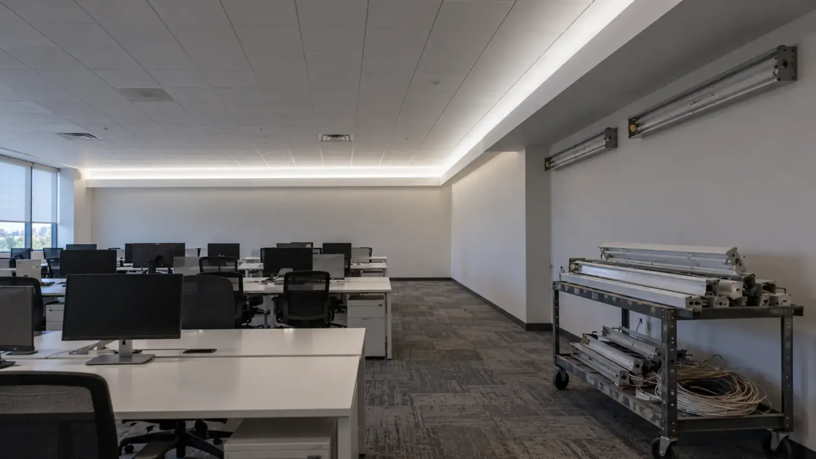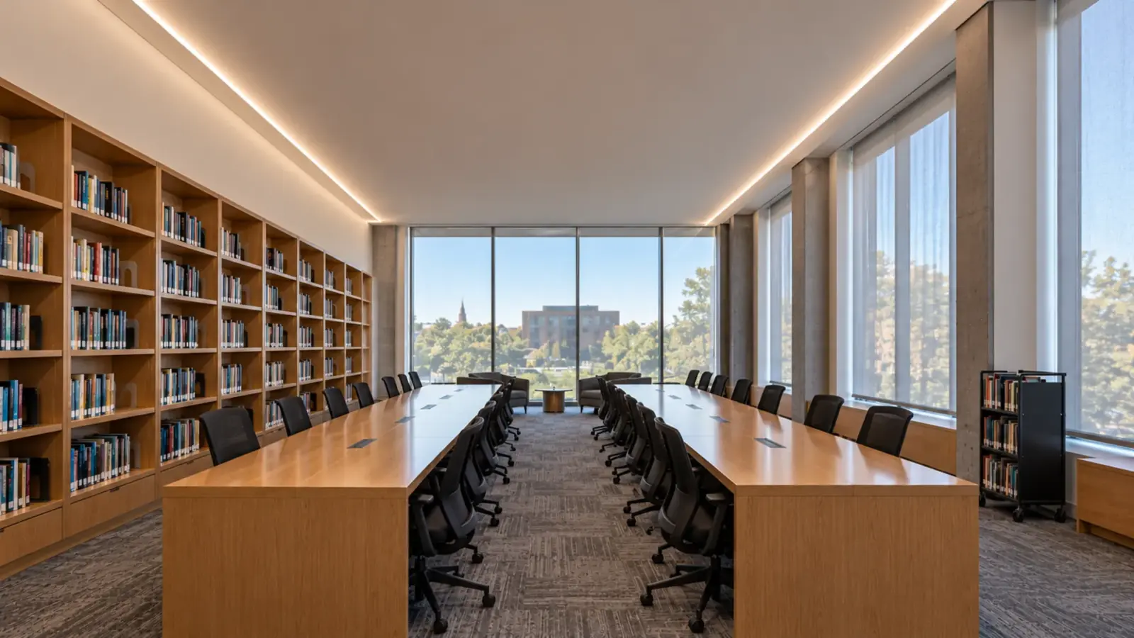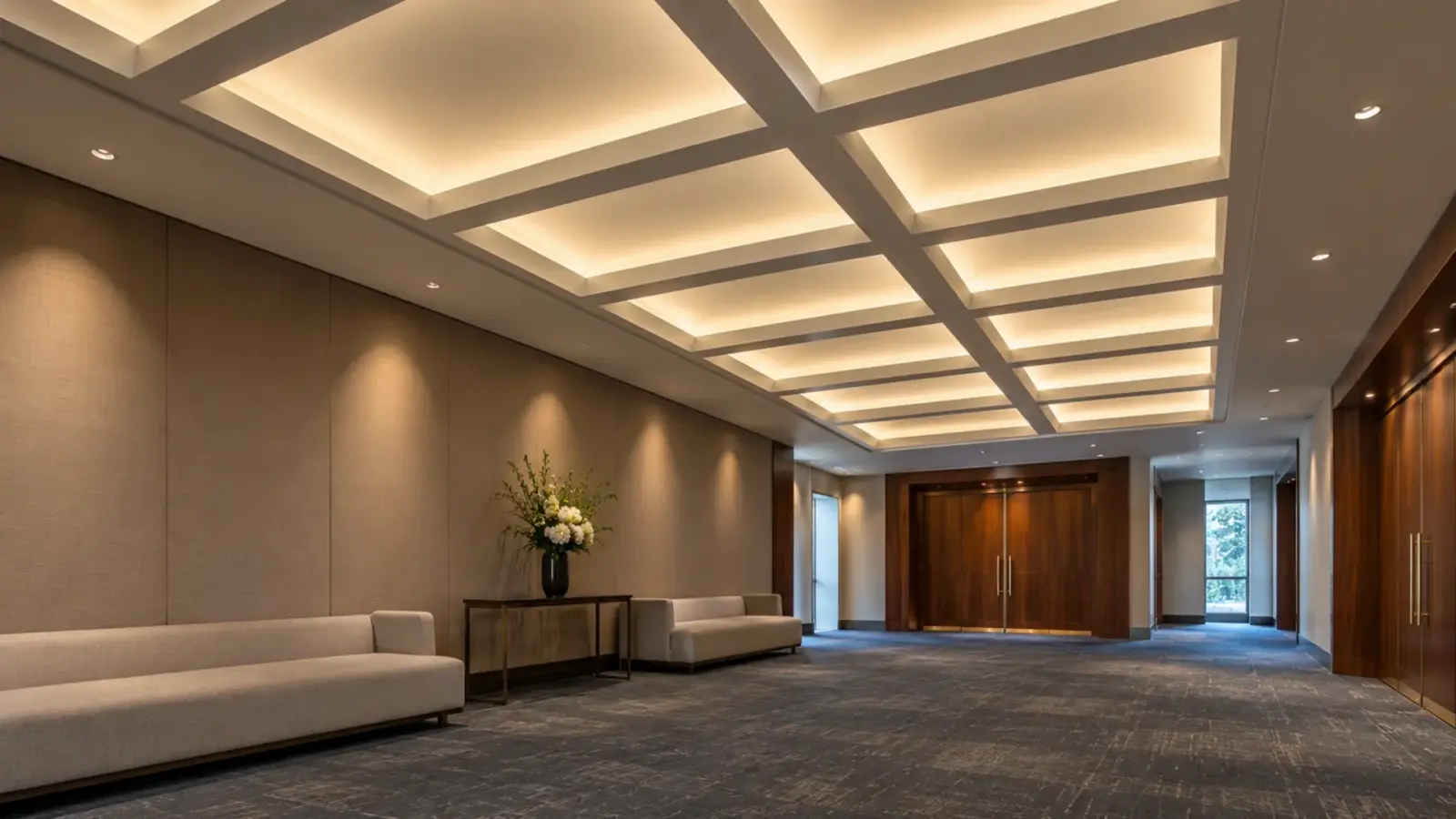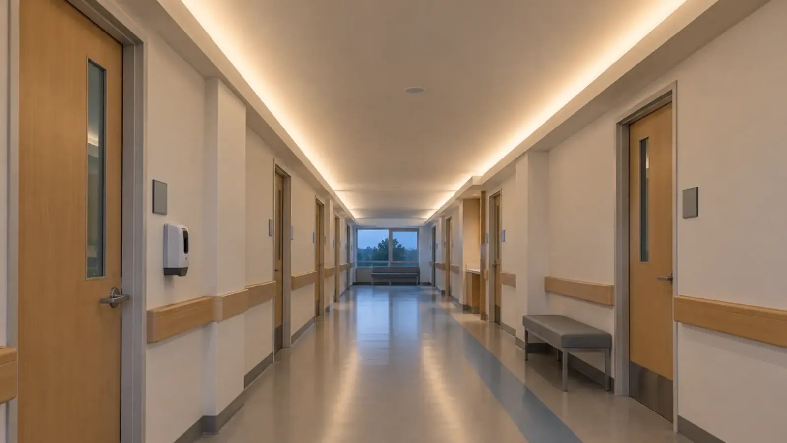
Start a cove section with every dimension at 150 mm (6 in), then change each one for a reason. Cove lighting dimensions come down to four numbers: the gap from the strip to the ceiling, the lip height, the strip’s setback behind the lip, and the pocket width for the channel and the wire.
The Four Numbers on a Cove Section
The 150 mm rule comes from Nulty Lighting, a lighting design consultancy, in a 2009 article written when LEDs were still new to coves: if every dimension associated with the cove is 150 mm, the detail “will be easy to maintain and enable light to escape whilst ensuring lamp sources are not visible.” The same article says cove dimensions are often governed “not by the illuminated effect or the lamp size but by the need to access and maintain the light source.”
- Gap: the vertical distance from the strip to the ceiling surface it lights. Our cove page calls this the setback, and it controls evenness.
- Lip height: the upstand in front of the strip, measured from the ledge. It controls what people can see.
- Strip setback: the distance from the lip’s inside face back to the strip. Vendors use “setback” for this one, so say which you mean on the drawing.
- Pocket width: the ledge from the lip face to the wall. It controls whether a crew can reach the strip.
Published figures disagree, and none comes from a standard. Read them by what each number is for. The Montreal figures are quoted as a search result showed them, because the page itself would not load, so treat them as a vendor range.
| Source | Gap to ceiling | Lip | Strip setback | What it says |
|---|---|---|---|---|
| Nulty Lighting, 2009 | every cove dimension 150 mm (6 in) | same | same | A starting rule for access and hidden lamps, written for fluorescent and early LED coves |
| Montreal Lighting guide | 150–250 mm (6–10 in) | 50–100 mm (2–4 in) | 40–75 mm (1.6–3 in) | “to avoid scalloping” |
| PacLights residential guides | 8–12 in; 6–12 in from the ceiling edge | not given | not given | Even distribution without hotspots |
| RPI Lighting Research Center, home lighting guide | top of the cove at least 18 in (46 cm) below the ceiling | cove base at least 6 ft 8 in above the floor | not given | A fluorescent-cove rule that Wikipedia repeats |
| Our cove page | 4 in (100 mm) minimum, deeper where the cove allows | set by the sightline | not given | The minimum assumes COB or a diffuser |
Gap: Distance Before Brightness
The gap decides whether the ceiling shows a smooth gradient or a row of scallops. Scalloping is a row of bright arcs, one per LED, on the surface above the strip, and it comes from strip that is too close to the surface or too sparse. A usual order of cure is distance, then denser dot-free strip, then an opal cover; our guides to dots showing through a diffuser and to clear, frosted and opal covers cover the last two.
Our cove page treats 4 in (100 mm) as the minimum gap, with dot-free COB or a diffuser at that distance, and says to go deeper where the cove allows. The vendor ranges above sit higher, 6 to 12 in, because a larger gap lets the light blend before it lands. Our COB vs SMD cove guide covers which strip suits which gap.
Two of the published rules also collide on a low ceiling. The Lighting Research Center’s home lighting guide, which Wikipedia repeats, puts the top of a cove at least 18 in below the ceiling and the base of the cove at least 6 ft 8 in (80 in) above the floor. Subtract: a 9 ft (108 in) ceiling leaves 10 in of cove between the two (108 − 18 − 80), and an 8 ft (96 in) ceiling leaves none (96 − 18 − 80 is −2). On an 8 ft corridor, start from a gap of 6 to 10 in with COB, mock it up, and set the lip from the sightline instead of from a rule.
A typical corridor shows the budget. With a 9 ft (108 in) ceiling and the ledge at 8 ft (96 in), a 15 mm (0.59 in) channel such as UT-CH2415 leaves a gap of roughly 11 in. That is inside the PacLights range, just above Montreal’s 6 to 10 in, and well above our 4 in minimum. Raising the ledge to 8 ft 6 in (102 in) to hide the cove better cuts the gap to about 5 in, which is above our 4 in minimum but below the vendor ranges, so that detail needs COB or an opal cover and a mockup.
Lip Height: Draw the Sightline
A lip hides the strip only from the positions someone checked. With the ledge 80 in or more above the floor, people standing in the room look up at a cove and see nothing but its underside. The sightlines that matter come from above the ledge: a mezzanine, a stair landing, a balcony, or a person standing close beside a low wall cove.
The lip height that hides the strip is geometry. Take the eye’s height above the ledge, the horizontal distance from the eye to the lip’s inside face, the height of the channel top above the ledge, and the distance from the lip face to the channel’s far top edge. Then:
lip height = (eye height above ledge × far-edge distance + channel height × viewing distance) ÷ (viewing distance + far-edge distance)
For our UT-CH2415, a surface channel 24×15 mm (0.94×0.59 in), set at an assumed 1.6 in (40 mm) behind the lip, the far top edge sits 2.5 in behind the lip and 0.6 in above the ledge. The lip heights that hide it, in inches:
| Eye above the ledge | Viewing distance 3 ft | 6 ft | 12 ft |
|---|---|---|---|
| 12 in | 1.3 | 1.0 | 0.8 |
| 36 in | 2.9 | 1.8 | 1.2 |
| 60 in | 4.5 | 2.6 | 1.6 |
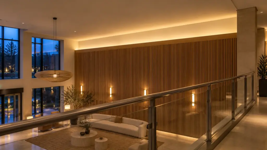
Take a double-height lobby with an 18 ft ceiling, a cove ledge at 16 ft on the far wall, and a mezzanine floor at the same level. A visitor at the rail has eyes about 5.5 ft above the mezzanine floor, which is 66 in above the ledge. Standing 8 ft back from the cove’s lip face, the lip must be 2.3 in tall. Pressed against the rail, 3 ft from the lip, it must be 4.8 in. Moving the channel 1 in closer to the lip, so the far edge sits 1.5 in behind it, brings the 8 ft case down to 1.6 in. The Lighting Research Center’s home lighting guide gives the same warning without numbers: if a landing or balcony overlooks a room with coves, shield the cove lamps from view from above. The vendor lip range of 2 to 4 in covers the 8 ft view, and fails for anyone standing close to the rail.
Read the table from the ledge, not from the floor. An eye below the ledge sees only the cove’s underside, so the first row starts at 12 in above it. A viewer’s eye sits about 66 in above the floor they stand on, so a landing level with the ledge puts the eye 66 in above it, past the last row, and the lip rises with it. The corner channel UT-CH1616 seats in the corner of the pocket and aims the strip at 45°; it is 0.63 in tall, and if its front sits 1.6 in behind the lip, its far edge is 2.2 in back, which gives the same calculation a slightly shorter lip.
The calculation hides the source, not the glow. When the sightline cannot be won with height or position, specify dot-free COB LED strip so that what shows is one continuous line, as our cove page advises.
Pocket Width: Fit the Channel and the Wire
Size the ledge for the channel, not the bare strip, as our cove page puts it. These are three channel sizes in our LED channels and diffusers range that suit coves, with UT-CH1013 the slim option:
| Channel | Size | Max strip width | Where it fits |
|---|---|---|---|
| UT-CH2415 | 24×15 mm (0.94×0.59 in) | 15 mm | Surface, deep dot-free |
| UT-CH1616 | 16×16 mm (0.63×0.63 in) | 10 mm | Corner, 45° aim |
| UT-CH1013 | 13×10 mm (0.51×0.39 in) | 10 mm | Surface, slim |
Build the pocket up from the front. With the strip 1.6 in behind the lip and a 0.94 in channel, the far edge sits 2.5 in back. Add the connector and the bend of the feed wire, which the connector you specified decides, and add room for a hand. Nulty’s 150 mm starting dimension, about 5.9 in, leaves about 3.4 in behind the channel in this example. Our cove page says to add room behind the lip for the feed wire and connectors, and to leave a way in: a joint buried in a sealed cove, or a driver above a plaster ceiling with no hatch, turns a ten-minute repair into a ceiling repair. Mark every joint and feed on the plan.
For heat in the same pocket, see our guides to channel thermal performance and to selecting a channel.
Corners, End Walls and Finishes
Nulty’s tips article says removing the upstand to make a shelf detail lets more light escape, which suits wall washing, and adds “be sure to check viewing angles into the cove. Particularly at corners if, for example you are wrapping the cove around a core wall.” Draw the sightline from the corner approach, not only from the middle of the room.
Inside surfaces matter too. Nulty recommends matt white paint inside the cove, a plywood insert where glass-reinforced gypsum leaves a messy surface, and an internal skin over ceiling support channels to avoid hot spots above them. Gloss paint, polished stone and glass can mirror the strip, so our cove page specifies COB wherever the lit surface or anything below the cove is glossy.
End walls follow the same rule as corners. Where a cove stops at a wall, a person standing near that wall can see the strip’s end cap and lead. Keep the lead behind the channel’s end cap, and mock up the end of the run before the whole cove is built. Plan each length to end at a corner or a hidden position, cut only at the marked cut points, and order the whole cove from one batch. Our guide to replacing a T8 cove covers an existing pocket whose dimensions are already fixed.
Dimensions to Put on the Drawing
- Gap from strip to ceiling surface, with the ceiling height and the ledge height above the floor.
- Lip height, and the sightline it was checked against: viewing position, eye height and distance.
- Strip setback behind the lip, measured to the channel’s far top edge.
- Pocket width, with the channel model, its size, the connector and a hand’s room.
- Joint, feed and driver locations, with the access route.
- The finish of every surface the strip lights or the lip shows.
The strip and channel models named above are in our cove lighting application page, with the section decisions that go with them.