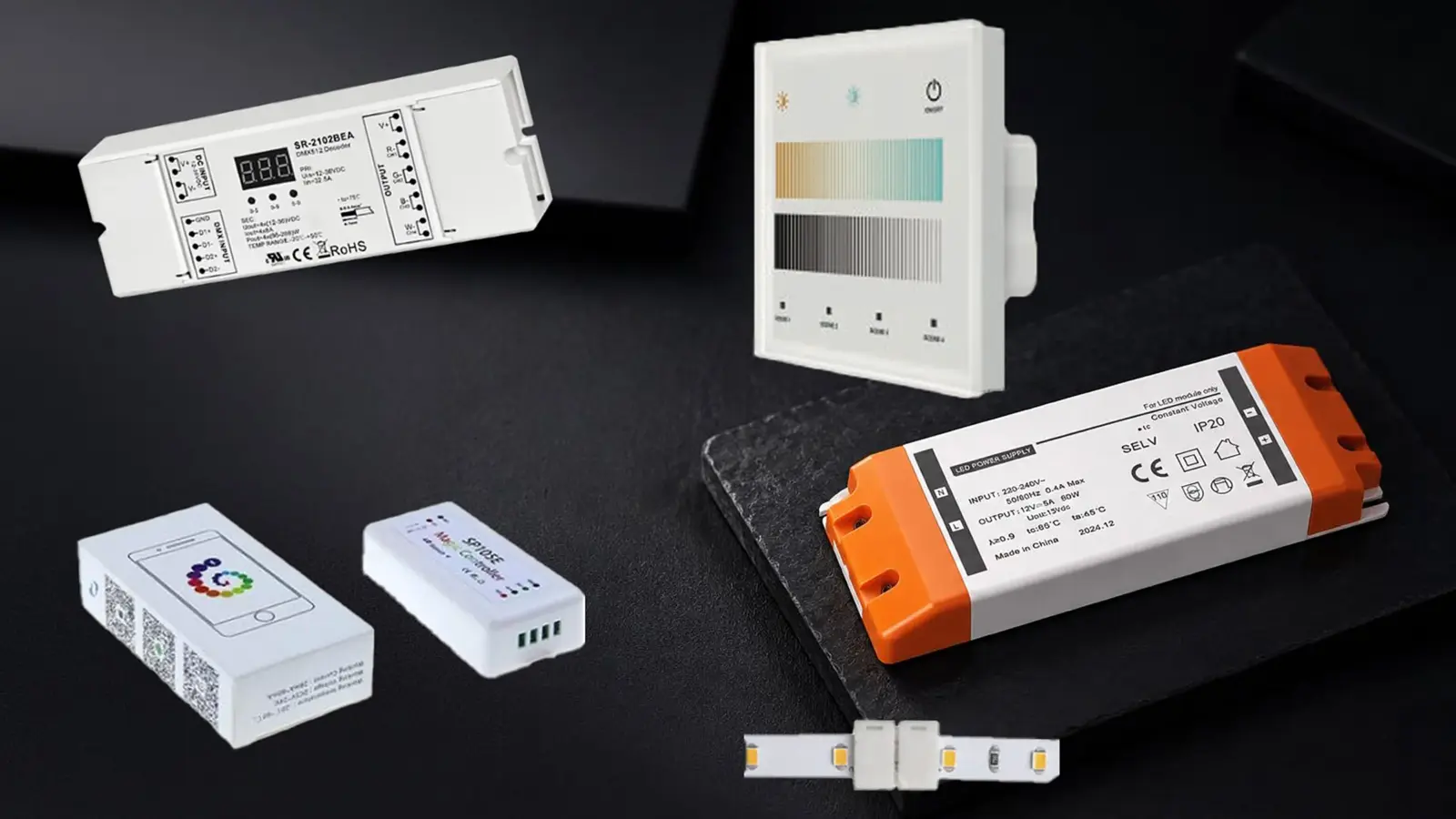
The photometric plan counted the stair cove toward the emergency average. The electrical drawings fed it from a normal panel. The walkthrough found out at the breaker, and the fix was a new circuit pulled through a finished ceiling on a Saturday.
LED strip emergency lighting is a question of what feeds the strip when the utility fails, and the answer has to be a device listed to UL 924: a load control relay on an emergency circuit, a battery emergency driver, or a listed inverter. The strip and its drivers carry no such listing; this page is about where the listing sits and the three ways to put it on the path.
What the Strip Is and Is Not
LED strip is a listed component or a listed system, depending on the product; it is not an emergency luminaire, and ours is not. UL’s Question Corner in IAEI Magazine draws the line for a related product, LED tubes with built-in batteries: they are not emergency lighting because they are user-replaceable and not fixed in place, and emergency luminaires are Listed to UL 924, the “Standard for Safety for Emergency Lighting and Power Equipment”, under category FTBR. The same reasoning reaches strip. A reel of tape with a driver is not an emergency luminaire until something listed to UL 924 is in its power path and the engineer of record has counted it in the egress design.
So two things have to be true before a strip run appears in the emergency calculation. The engineer has designed it in, at the levels our stair egress guide sets out from Consulting-Specifying Engineer’s reading of the codes: 0.1 fc minimum, 1 fc average, no more than 40 to 1. And a UL 924 device feeds it on loss of normal power. The strip’s own listings, which our UL listings guide explains, say nothing about emergency use; our drivers’ listing options are held by our manufacturing partners and documented on request, and none of them is a UL 924 listing.
Three Paths to Power in an Outage
| Path | What carries the UL 924 listing | What the strip and driver must be | Dimming in the outage | Typical use |
|---|---|---|---|---|
| 1. Emergency circuit (generator or central inverter) with an automatic load control relay | The ALCR; the inverter if used | Any strip; a driver with no control input used for the bypass, or a driver listed as a directly controlled luminaire | Forced to full by the relay | Corridor and stair coves on buildings with an emergency system |
| 2. Battery emergency driver per segment | The emergency driver | A short dedicated 24V segment sized to the driver’s watts | Full output from the battery driver | Single stairs, small buildings, remote segments |
| 3. Listed inverter feeding 120V strip | The inverter | Direct-AC strip with no driver and no control input | None; on at full | Stair runs and corridors where line-voltage wiring suits |
The paths are not interchangeable. Path 1 needs an emergency system to exist. Path 2 is self-contained but short. Path 3 trades the low-voltage strip’s color quality and cut interval for a system with no driver to list.
Path 1: Emergency Circuit and a UL 924 Relay
In a building with an emergency system, a generator or a central inverter feeds emergency panels, and NEC Article 700 governs the wiring and its separation from normal circuits. The strip’s driver is fed from an emergency circuit, but the room’s switch or sensor still has to be able to turn the cove off on a normal day, which is what the automatic load control relay is for. Consulting-Specifying Engineer notes that these relays must carry a UL 924 listing (the IAEI article treats them as the control devices of 700.24); the manufacturers’ literature describes the function the same way: the relay senses loss of utility power and switches the emergency load to full, bypassing the normal switches and dimmer controls, with dry contacts that, in Functional Devices’ words, “override 0-10 V dimmers to full brightness”, a return-to-normal delay of 0 to 15 minutes, and a test button or self-diagnostics.
For strip that means a cove on an emergency circuit, its driver’s line through the ALCR, and its wiring kept to the emergency raceways; our NEC guide covers the Class 2 side. The ALCR is also what makes the dimmed cove useful: at 1 a.m. the corridor sits at its night level, and in an outage the relay drives it to full. Which brings in the trap.
The 0-10V Trap: Directly Controlled Luminaires
The 2014 NEC added 700.24, which the IAEI article by Craig Lanham and Steve Terry quotes: “such luminaires and external bypass controls shall be individually listed for use in emergency systems”. The 2017 NEC defined the luminaire in question, a directly controlled luminaire, as one with “a control input for an integral dimming or switching function that drives the luminaire to full illumination”. The authors draw the consequence for dimmable LED gear: “Those 0-10V control inputs now qualify the driver or luminaire as a Directly Controlled Luminaire”, and it has to be UL 924 listed; and “control devices that participate in the activation of emergency luminaires upon loss of normal power” need the listing too.
The same article offers the way around it for simple gear: a luminaire dimmed on the line, by an external dimmer, “does not need a separate UL924 evaluation in order to be used as an emergency luminaire”. For strip the reading is this. If the relay’s bypass works by forcing the driver’s 0-10V input to full, the driver is being used as a directly controlled luminaire and, on the 2014 and 2017 reading above, needs its own UL 924 listing; our 0-10V driver has none. The 2023 NEC loosens this: its 700.24, retitled Directly Controlled Emergency Luminaires, says in ETC’s reproduction that luminaires energized to the required emergency level “by disconnection of their control input by a listed emergency lighting control device shall not be required to be listed for use in emergency systems”, so under the 2023 edition a driver pushed to full by a listed relay that opens its 0-10V lead no longer needs its own listing; the earlier reading applies where those editions are adopted. If instead the relay switches the driver’s line and the driver has no control input in the emergency path, a non-dim driver such as UT-D60-24-C2 on an emergency circuit through the ALCR, the luminaire-listing question is the line-dimmed one, and it is the AHJ’s determination whether the strip assembly is accepted that way. Settle it with the AHJ and the engineer before the drivers are bought, and write the answer on the drawings.
Path 2: A UL 924 Battery Driver per Segment
Where there is no emergency system, or a single stair sits far from one, a UL 924 battery emergency driver does the whole job: it charges from the normal circuit, and on loss of power it feeds its output for 90 minutes from its own battery. The two makers’ product pages describe constant-voltage and constant-power units: a 14 W model with a 15 to 54 V DC output and 20 W models with 20 to 60 V DC or 54 to 200 V DC outputs, the Bodine pages adding that the unit switches “to emergency mode for 90 minutes of backup” and returns to charge when power returns.
The arithmetic is what decides the design. At 24 V, 14 W holds about 5.8 ft (1.8 m) of UT-C320-8 at 2.4 W/ft; 20 W holds about 8 ft (2.4 m). An emergency battery driver therefore feeds a short, dedicated segment, not the whole cove: the strip at the stair landing, the 6 ft over the exit door, the run along the first flight, each on its own battery driver with its own segment, while the rest of the cove stays on the normal driver. Confirm the strip’s voltage sits inside the emergency driver’s output range and that the driver’s rated watts cover the segment at full output; the maker’s data sheet governs, and the segment’s separation from the normal run is a cut point and an end cap. Our COB LED strip page lists the cut intervals that set where a segment can end.
Path 3: A Listed Inverter and 120V Strip
The third path removes the driver. Direct-AC strip such as UT-H120-120 runs from 120 V with no driver and no control input, 98 ft (30 m) from a single feed, and a UL 924 listed inverter on the emergency side feeds its circuit; one maker’s literature describes a 1.5 to 14 kW line with “a peak overload capability up to 1400% to accommodate inrush current from LED fixtures” on its top model, and David Shiller’s Buildings column on emergency tubes makes the case for “a hardwired emergency inverter that is UL 924 listed” over battery-equipped lamps. The inrush point is real for strip too: a long direct-AC run and its rectifiers draw a surge at transfer, and the inverter is sized for it or, as one emergency-lighting maker’s technical note warns, the surge can exceed its rating, “causing premature shut-down of the system”.
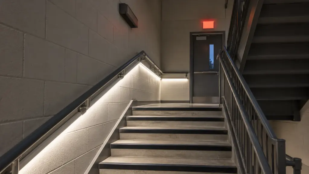
What path 3 costs is the low-voltage strip’s qualities: the 120V families are Ra≥80 and cut every 19.7 in (500 mm) on the SMD version, per our 120V vs 24V guide, and the circuit is wired with line-voltage methods confirmed with the AHJ. In a stair that is lit for safety and not for finish, that is a fair trade, and the luminaire-listing question is again the line-powered one for the AHJ. Our 120V LED strip page lists the families and their single-feed lengths.
Where It Goes: Stairs, Corridors, Exterior Steps
Not every run needs emergency power; the egress design names the ones that do. A hospital corridor’s cove usually has one wall’s run on the emergency path and the other on normal power, so the corridor stays lit in an outage without doubling the emergency load; our hospital guide places the runs. A student housing or apartment stair hall puts its landing and flight runs on path 2 or path 1 and leaves the lounge cove normal. An exterior egress stair uses the IP65 strip, UT-O320-8-65, with its wet location marking confirmed at quote and its battery driver or ALCR indoors in a dry box.
Two rules for the drawings. Mark every emergency run with its path and its listed device on the lighting plan, so the inspector can follow the listing from the strip to the relay, driver or inverter. And keep the emergency segments physically separate from the normal runs, with their own feeds and end caps, so a later tenant’s electrician cannot splice the two; our cutting and listing guide explains what field changes do to a listed system.
FAQ
Can LED strip be used for emergency lighting?
Only as part of a design the engineer counts and a power path with a UL 924 listed device: an automatic load control relay on an emergency circuit, a battery emergency driver, or a listed inverter. The strip and its drivers carry no UL 924 listing of their own, ours included.
What is UL 924?
The UL Standard for Safety for Emergency Lighting and Power Equipment. Emergency luminaires, load control relays, battery emergency drivers and lighting inverters are listed to it; a strip system borrows its emergency standing from the listed device in its power path.
Can a 0-10V dimmable driver be on an emergency circuit?
Only with care. If the emergency bypass works through the driver’s 0-10V input, the IAEI article’s 2017 reading is that the driver is a directly controlled luminaire and needs a UL 924 listing; the 2023 NEC exempts a luminaire driven to full by a listed control device that disconnects its control input. A driver switched on its line by a UL 924 relay, with no control input in the emergency path, avoids the question in either edition; confirm the adopted edition with the AHJ.
How long must emergency lighting stay on?
Ninety minutes is the figure the battery emergency drivers and the inverters are built to, and it is what the inverter literature cites as the code minimum (Consulting-Specifying Engineer points to NFPA 101 7.9.2.1 and IBC 1008.3, 1½ hours). The adopted building code and NFPA 101 edition in your jurisdiction govern.
What to Verify With the AHJ
- Which strip runs the engineer counts in the emergency design, and at what levels.
- Which path feeds each one, and which device on that path carries the UL 924 listing.
- Whether a 0-10V driver sits in any emergency path, and if so whether it needs its own listing.
- Whether a strip assembly fed on its line from a listed device is accepted as emergency illumination in this jurisdiction.
- The emergency wiring separation, the ALCR test method and the return-to-normal delay.
- The battery emergency driver’s output range and watts against each segment.
The COB and 120V strips named here are in our COB and 120V LED strip ranges, with the drivers’ listing documentation available on request; send the egress plan with the emergency runs marked and we will set the segment lengths and cut points for each path.