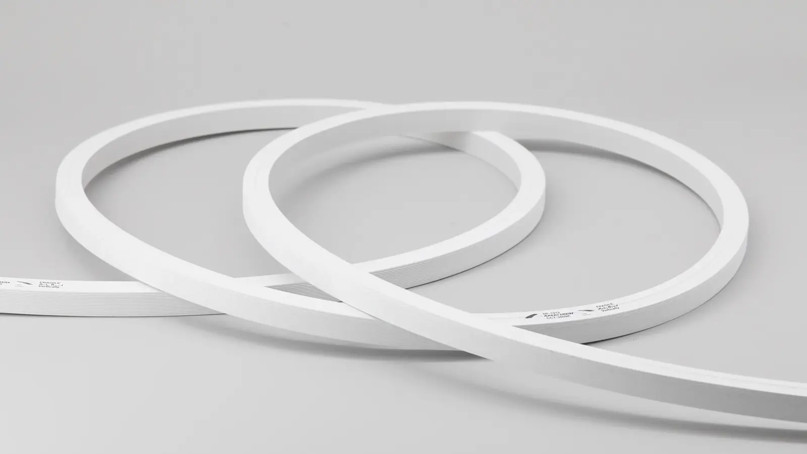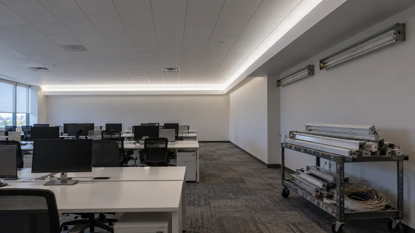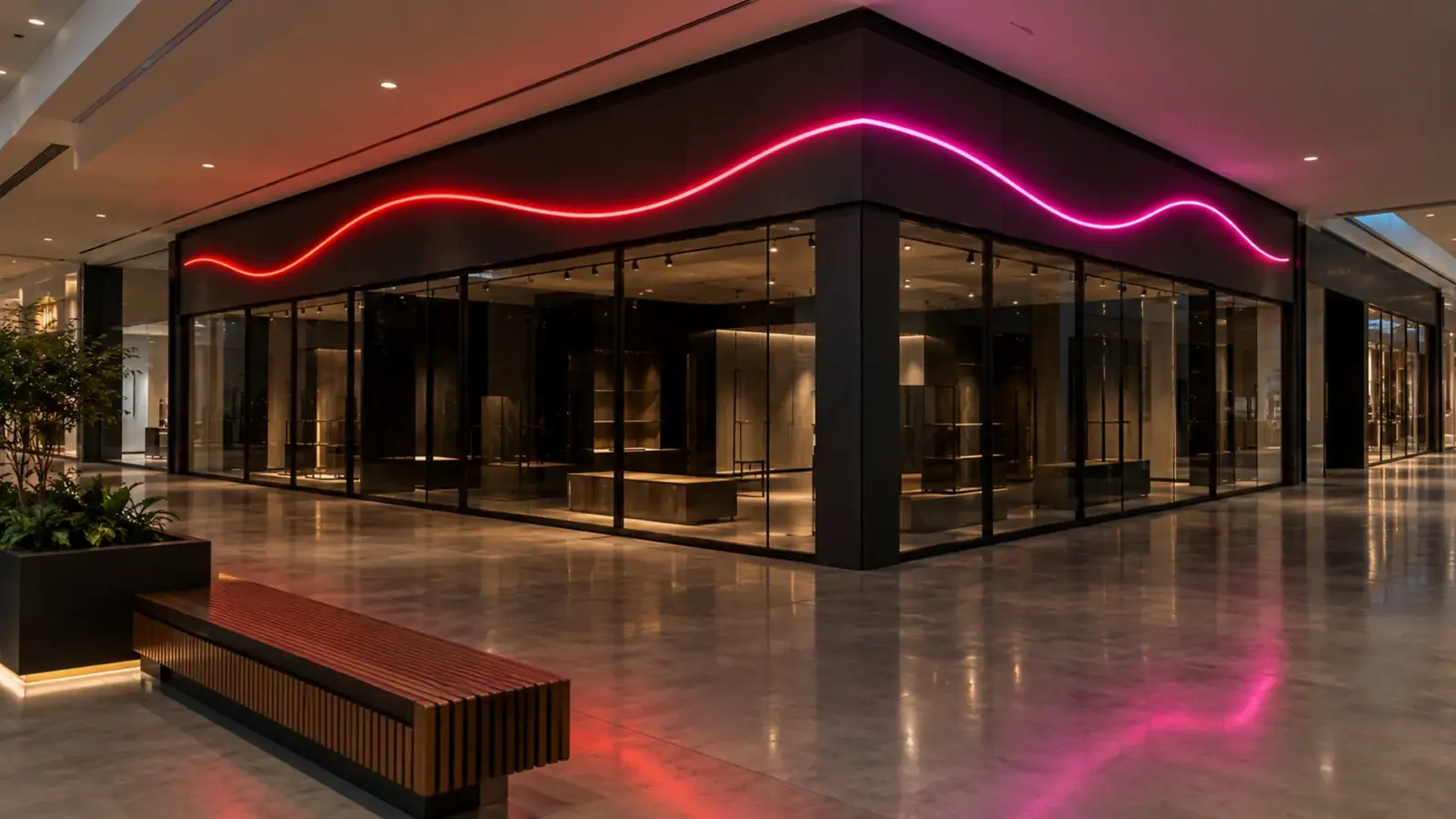
A neon wave drawn at 10 ft 9 in arrives at about 10 ft 6 in, and the corner gap shows across the mall. Neon flex is cut only on its marks, so the lit length lands on the last mark below the drawn length. Drawing LED neon flex lead exits, cut increments and dark ends to scale prevents it.
The rules below are the ones our assemblies are built to, with the numbers from our neon profiles. They work for anyone’s neon, because every profile has a cut step, two ends and a lead that has to go somewhere.
The Cut Step Sets the Lit Length
Every neon profile is cut on printed marks: every 3.94 in (100 mm) on our standard profiles and 1.97 in (50 mm) on the nano series. Our assembly rule is plain: “The lit length is cut on the nearest cut mark at or below the drawn length, never longer.” A drawn length between two marks is built to the mark below it.
How much that costs depends on the step. Take one drawn piece, 10 ft 9 in (3,277 mm), and build it on six of our profiles:
| Profile | Cut step | Lit length built | Short of the drawing |
|---|---|---|---|
| 100 mm-step profile, e.g. UT-N1616-TB | 3.94 in (100 mm) | 125.98 in (3,200 mm) | 3.02 in |
| Large profile UT-N5025-TB | 3.27 in (83 mm) | 127.44 in (3,237 mm) | 1.56 in |
| Nano UT-NN12, CSP rows | 1.97 in (50 mm) | 127.95 in (3,250 mm) | 1.05 in |
| CSP RGB UT-CSP-540-N12-RGB | 1.31 in (33.3 mm) | 128.48 in (3,263 mm) | 0.52 in |
| Free-cut side-emitting UT-N0306-S | 0.39 in (10 mm) | 128.74 in (3,270 mm) | 0.26 in |
| Mini-cut side-emitting UT-N0408-S-MC | 0.28 in (7.14 mm) | 128.74 in (3,270 mm) | 0.26 in |
On a standard profile the shortfall can approach a full step, just under 4 in. Two fixes work. Draw lengths that land on the step, by moving a corner or a lead point a few inches where the architecture allows; or choose a finer-step profile where the line has to close exactly. Our neon flex table lists the cut step for every model, and the assembly drawing we return shows each lit length before anything is cut.
Lit, Overall and Tolerance
A piece has two lengths, and a drawing that gives only one invites argument. The lit length is the part that glows, set on the cut marks. The overall length is the lit length plus the end caps at both ends, the dimension the installer actually fits between two points.
Our assemblies hold “Overall length, end caps included… to plus or minus 1/4 in (6 mm) unless a tighter value is agreed on the drawing.” Put three numbers on every piece: drawn overall length, lit length on the marks, and the tolerance. The installer fits the overall length; the designer judges the lit length; the tolerance tells both what counts as right. If a detail needs tighter, write the tighter value on the drawing; a recessed channel with fixed end stops is the usual case.
Cap length varies by profile and by maker, and our pages do not publish it per profile. Do not guess it for a tight detail: the first article, below, is where it gets measured.
Dark Ends and Joints
Every piece has two ends where, on most profiles, the light stops a little before the physical end: the cut is made between LED groups, and a cap closes the profile beyond it. A single piece hides that in a channel end or behind a return. Two pieces butted together show it as a short dark gap, and at eye level on a storefront that gap is the first thing people see.
Three ways to keep it off the facade:
- Bend through corners instead of joining at them. A top-bend profile such as UT-N1616-TB bends to a 3.15 in (80 mm) radius; a side-bend UT-N0612-SB to 4.72 in (120 mm). A corner no tighter than that radius is one piece and no gap. Our bend selection guide matches the profile to the curve.
- Put the joints where the eye does not land. Behind a column, at a change of plane, inside a sign return.
- Use caps that pass light where the end shows. Some makers sell clear silicone caps; Tagra describes one as “transparent allowing for the light to pass through even at the very end of the neon flex.”
Every end is also a seal. Our pieces have each end “closed with a matching end cap and sealant, cured before testing”, and our cut-end sealing guide explains why the cut end is the weak point outdoors.
Where the Lead Leaves: End, Back or Side
The lead exit decides where the hole goes, how the piece mounts and whether the lead shows. Our assemblies offer “End, back or side exit where the profile allows it”:
| Exit | Use it when | What the drawing must show |
|---|---|---|
| End | The piece ends at a wall, a return or a channel end with space behind it | The lead’s route from the end and the clearance it needs to turn |
| Back | The lead should disappear through the mounting surface, as on a fascia or a sign face | The hole position measured from a fixed end, and the hole size for the lead |
| Side | Typically side-emitting or side-bend profiles in channel letters and returns, confirmed per profile on the assembly drawing | Which side, and where the lead meets the return |
The lead carries one conductor per circuit: 2 for single color, 3 for tunable white, 4 for RGB and 5 for RGBW on our assemblies, so an RGBW lead needs a bigger hole and a bigger gland than a mono one. Leads come at 3.3 ft (1 m) unless drawn longer; draw them longer when the driver sits in a sign cabinet or above a ceiling. A back exit drilled from a drawing dimension measured from the wrong end is a hole in a finished fascia, so dimension it from the end the installer will start at.
Channel letters are the tightest case. A side-bend profile follows the letterform, the lead has to leave where the return can take it, and every letter is its own piece with its own lead; our halo-lit vs face-lit guide covers how the lighting choice changes the letter’s depth and access, which in turn decides where those leads can go.
Feed End and Run Limits
The lead exit is also the feed end, and the profile’s run limit decides how many feeds a line needs. Our standard 24V profiles run 16 ft (5 m) per feed; constant-current profiles run 49 to 98 ft (15 to 30 m), for example 82 ft (25 m) on UT-N1616-SB. A storefront line longer than the limit is either fed from both ends or split into pieces with their own leads; our reel vs run guide works through both.
Mark the fed end on every piece, and draw the second lead where a piece is fed from both ends. A piece with its lead on the wrong end turns a 3.3 ft lead into one that does not reach the driver.
Shapes, Templates and the First Article
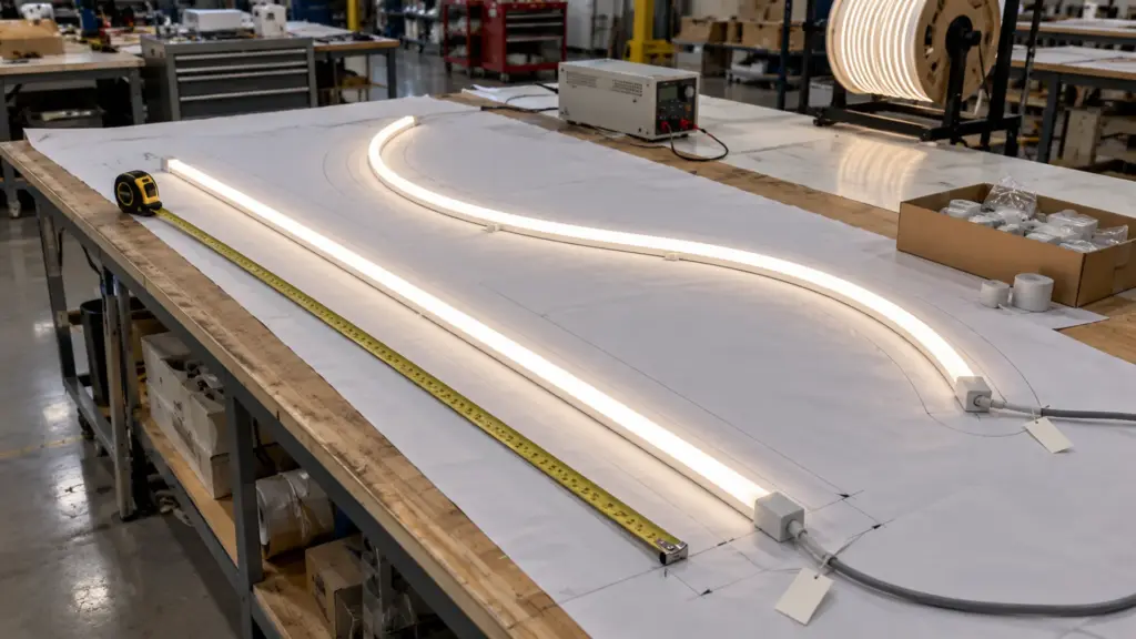
Shaped neon needs a shape on paper. For neon formed to a curve, our assembly page asks for “a full-size template or a scaled drawing with the radii marked”, and the radius has to stay inside the profile’s rating, in its bend direction. Mark which face lights, so a side-bend piece is not formed the wrong way.
Then one piece of each type is built and sent lit, with its end caps and leads as drawn, before the rest are made. That first article is where you check what a drawing cannot show: the cap length, the dark end at each cap, the color and brightness against the mockup, and whether the lead reaches. The approved piece becomes the reference; the rest are built to it, tested lit and labeled with their ID from the drawing. Our installation guide picks up from there, on site.
A Worked Piece List
Here is how three pieces for a typical hotel bar back look once the rules are applied, on UT-N1616-TB with its 3.94 in (100 mm) step and single-color leads:
| Piece | Space available (drawn) | Lit length on the marks | Exit and feed | Lead |
|---|---|---|---|---|
| BB-1, top shelf | 8 ft 2 in | 7 ft 10.5 in (2,400 mm, 24 steps) | Back exit, fed at the left end, hole 2 in from the left end | 6 ft to the driver in the base cabinet |
| BB-2, middle shelf | 8 ft 2 in | 7 ft 10.5 in | Same as BB-1 | 6 ft |
| BB-3, arch over the mirror | Template, 9 ft 4 in along the curve | 9 ft 2 in (2,800 mm, 28 steps) | End exit at the left foot | 3.3 ft standard |
The lit lengths are shorter than the space by design: each sits on its last mark. The built overall length is the lit length plus two caps, given on the assembly drawing and confirmed on the first article, and the ±1/4 in tolerance applies to that built figure; the leftover space at the ends is the installer’s to center or to hide behind a return. The bartender sees three unbroken lines; the installer gets three labeled pieces with the holes already decided. Where shelves have to read as equal lines, draw them equal on the step, as BB-1 and BB-2 both land on 24 steps, rather than equal on a dimension that one of them misses by a mark. The arch gets a template because its length is measured along the curve, which a straight dimension cannot describe.
On delivery, each piece “carries its ID from the drawing and is packed by area or by elevation”, with the drawing and a piece list in each carton, so the crew mounts BB-1 where BB-1 goes. That labeling is worth asking for on any neon order, because pieces of the same profile look identical once they are out of the box.
The Piece List, Checked
- Every drawn length checked against the profile’s cut step; corners and lead points moved where a few inches close the gap.
- Lit length, overall length and tolerance on every piece.
- Joints placed out of sight, or corners bent instead of joined.
- Lead exit, end, back or side, with the hole dimensioned from a stated end.
- Lead length to the real driver location; conductor count for the color type.
- Fed end marked; both-end feeds drawn where the run limit requires.
- Full-size template for shaped pieces, with the lit face marked.
- First article approved before production.
Unitop Lighting builds neon and strip to the drawing on our custom neon assemblies service: cut on the mark, wired, sealed, tested and labeled per piece. Send the elevation or the piece list with the lead exits marked and we will return an assembly drawing for each piece type with the lead time: request a quote.