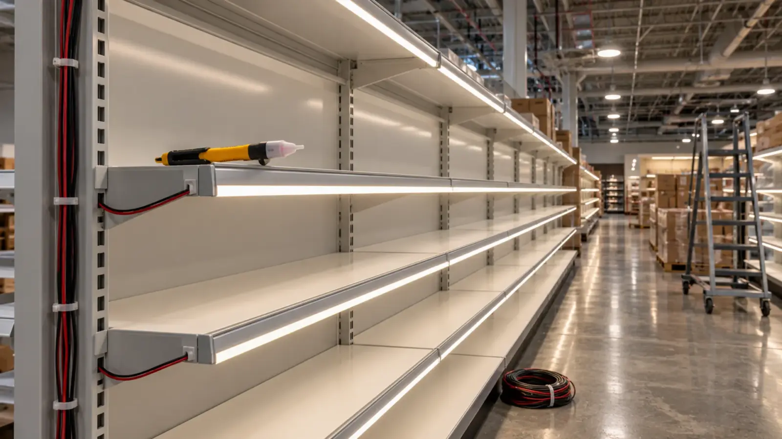
“Does the aluminum channel need a ground?” The inspector asks it at the final, flashlight on a 60 ft run of 24V strip. For an aluminum LED channel housing Class 2 strip the answer is no: the circuit’s secondary is not grounded by rule, so there is no equipment grounding system for the channel to join.
The answer changes when the strip is 120V or the channel shares space with line-voltage conductors. The ladder below runs from the first “why” to what to say at the final.
Why the Secondary Is Not Grounded
Start with the supply. A Class 2 driver is an isolating power supply: its 24 V DC output is separated from the 120 V input, and the output circuit is not referenced to earth. The National Electrical Code’s low-voltage lighting article has said so since at least the 1999 text read here. Frederic Hartwell’s EC&M commentary on the new Article 411, written for the 1999 code, put it this way: Section 411-5(a) “prohibits grounding this circuit”, you “cannot intentionally connect one of the conductors ‘to earth or to some conducting body that serves in place of the earth'”, and the isolating transformer’s grounded barrier does not mean the secondary is grounded. A 2015 Mike Holt forum reply on what was then 411.6 (411.7 in the 2023 NEC) says the same: “the secondary of the supply transformer shall not be grounded”. The 2023 text adds one exception, in NFPA’s second-draft wording: a Class 2 power source “listed and identified as suitable for secondary grounding” may be grounded, so the rule is “not grounded” unless the driver’s listing says otherwise.
That is the whole root of the channel question. Equipment grounding exists to give a fault on a grounded system a path back to the source so the overcurrent device opens. An ungrounded 24 V secondary has no such path and no such device; Hartwell’s 1999 conclusion was that “these lighting systems don’t require any provisions for equipment grounding”, and an Electrical Contractor magazine explainer written to the 2008 NEC reads 250.112’s list item (I) the same way for ungrounded low-voltage supply systems. Bonding the channel to the building’s equipment grounding conductor would not create a fault path for the strip; it would only tie a piece of aluminum to earth for no electrical purpose.
What Article 411 Says, and What It Does Not
Article 411 covers lighting systems at 30 V ac or 60 V dc and below; the 2023 NEC moved those limits from the scope into a new 411.3, which Leviton’s Captain Code summary quotes: the system and its components “shall not exceed 30 volts ac or 60 volts dc”, and 15 V ac or 30 V dc “if wet contact is likely to occur”. Our 12V, 24V and 48V strip sits inside the first limit; the wet-contact limit is the one our shower niche guide works through.
What 411 does not do, as the Mike Holt reply notes, is “address the actual metal parts of the fixture”. It forbids grounding the secondary and it requires a listed system installed per its instructions; it says nothing about bonding a channel, because on an ungrounded secondary there is nothing to bond it to. The practical reading is the one the inspector needs: on a Class 2 run, the listing and the installation instructions of the strip and its driver govern, and our NEC guide walks through the Class 2 side of the installation. The edition matters; the 2023 wording differs from 2014 and from 1999, and the adopted edition in the jurisdiction is the one the inspector is reading.
The Sign Rule Inspectors Borrow
The closest the code comes to a direct answer is in Article 600, for signs, and inspectors often reason from it. Roger Rumsey’s IAEI inspection guide for LED signage, written to the 2014 NEC, answers the bonding question for sign components: not required “if the circuit between the power source and LED sign component is less than 50 volts dc” and “the conductors are not intermingled with other power or electric light circuits”. The exception he quotes, 600.7(B)(1), reads: “Remote metal parts of a section sign or outline lighting system only supplied by a remote Class 2 power supply… shall not be required to be bonded to an equipment grounding conductor”.
An aluminum strip channel on a shelf is not a sign, and 600 does not govern it. But the two conditions in the sign rule are the two that matter anywhere: the voltage, and whether the low-voltage conductors are kept apart from power circuits. Where both hold, the code’s own treatment of remote metal parts on a Class 2 supply is that they need no bond. Where either fails, the question is live.
When the Strip Is 120V
| What is in the channel | Supply | The bonding question | Code path |
|---|---|---|---|
| 24V or 12V strip, Class 2 driver remote | Ungrounded Class 2 secondary, 60 V dc or less | No equipment grounding system to join; the sign rule’s two conditions hold | Article 411 and the Class 2 rules of Article 725 (cable rules move to 722 in the 2023 NEC); listing instructions; AHJ |
| 48V COB strip (UT-C480-8-48V), Class 2 or listed 48V supply | Still under the 60 V dc line | Same as above | Same |
| 24V strip, but the Class 2 driver sits inside the channel cavity or an attached enclosure | Line voltage enters the channel space | The channel now encloses line-voltage conductors and terminations | Article 250 bonding of enclosures; the driver’s listing; AHJ |
| 120V direct-AC strip (UT-H120-120) in a metal channel | Line voltage along the whole run | A metal enclosure around line-voltage conductors | Article 250; wired “with line-voltage methods like any other 120V load”; AHJ |
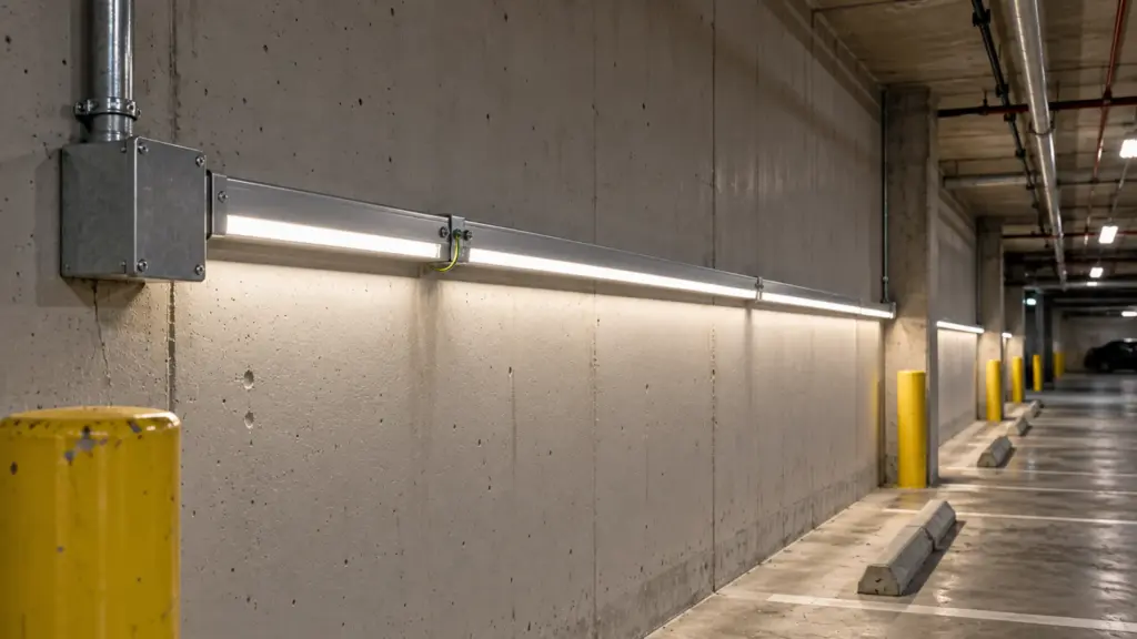
The 120V row is the real contrast. Direct-AC strip carries line voltage along its length, with no isolating driver between it and the panel; our 120V page says it plainly: it “runs on line voltage, so the Class 2 rules that cover 24V strip do not apply”, it is “wired with line-voltage methods like any other 120V load”, and the method is confirmed with the AHJ. A metal channel around a 120V strip is a metal enclosure around line-voltage conductors, and Article 250’s rules for enclosures and for metal parts “likely to become energized” are what the inspector will cite. Treat it as you would any metal raceway or enclosure on a 120 V circuit: an equipment grounding conductor to the channel, continuity through the run, and the connection made at a box. Our 120V vs 24V guide lists the electrician, the permit and the inspection among the costs of the driverless path; the bonding is part of that work.
The Channel Next to Line Voltage
The third row of the table is the one that catches good installers. A 24V strip in a channel is Class 2, but the channel is aluminum, it is 20 ft long, and at one end someone has mounted the driver inside the same cavity, or the channel’s lead enters a box that also holds the 120 V branch circuit. Now the sign rule’s second condition fails: the low-voltage conductors are intermingled with a power circuit, and the channel is part of an enclosure that contains line-voltage terminations.
The code’s answer for enclosures is in Article 250, and the Class 2 article’s answer is separation: Class 2 conductors are kept out of enclosures with power conductors unless a barrier or a listed arrangement permits it, which our in-wall wiring guide covers for cable and boxes. For the channel the practical rule is to keep the driver out of it. A driver belongs in its own box or on its own mounting, with the 24 V leads entering the channel and nothing else; our Class 2 driver guide explains what the inspector reads on the driver and why its output wiring method is confirmed with the AHJ. Do that, and the channel is back in the first row, a remote metal part on a Class 2 supply.
Anodizing, Clips and Continuity
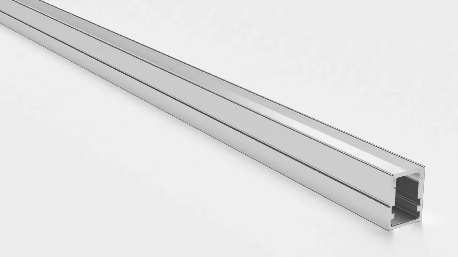
A note the inspector may raise and the datasheet may not. Our channels are AL6063 with an anodized finish, held by clips at 19.69 in (500 mm) and joined end to end with the makers’ straight connectors, which the profile trade sells as grub-screw or slide-in aluminum joiners and which no profile maker we checked describes as an electrical connection; the covers are polycarbonate. Anodizing is an oxide layer, and it does not conduct well, so even if a bond were wanted, a lug on one 2 m length would not bond the next length through the joint. One European profile maker’s datasheets recommend “a braided cable from the profile base to the dissipation tray” inside its own two-part profiles; that is a maker’s practice for its product, not a code requirement, and it says nothing about earth.
The point for the final is simple: a channel on a Class 2 run is a heat sink and a mounting rail, as our channel guide explains, and it is treated as one. Where a bond is actually required, as on a 120V strip, the channel has to be made continuous on purpose, with bonding jumpers across joints or a bonding conductor run with the circuit, because the finish will not do it.
What to Tell the Inspector
Say what the circuit is and show it. The strip is a listed low-voltage product on a Class 2 driver whose output is 24 V DC; the driver is remote, in its own box; the channel contains only the strip and its 24 V leads; and the secondary is not grounded by rule, so there is no equipment grounding conductor for the channel to join. Have the driver’s listing and the strip’s installation instructions on the lift with you, added to the items in our install checklist, and have the sign guide’s two conditions in your head: under 60 V dc, and not intermingled.
If the inspector asks for a bond anyway, do not argue the point on the ladder. Ask which section and which edition, because the answer differs between 1999, 2014 and 2023 texts, and because the AHJ’s determination is the one that counts in that building. Where the request is reasonable because the channel does share space with line voltage, fix the separation rather than the channel: move the driver out, and the question goes away with it.
The Short Version
- A 24V or 12V strip in an aluminum channel on a remote Class 2 driver has an ungrounded secondary; there is no equipment grounding system for the channel to join, and the sources read here say none is required.
- The two conditions that keep it that way come from the sign article: under 60 V dc (the sign guide’s figure is 50), and not intermingled with power circuits.
- A 120V direct-AC strip in a metal channel is a line-voltage enclosure: bond it like any other, with jumpers across the joints.
- A driver inside the channel cavity or a shared box puts line voltage in the channel’s space; move the driver out.
- Anodized aluminum does not make a bond through its joints; where a bond is required, make it on purpose.
- The adopted NEC edition and the AHJ govern; name the edition before you cite a section.
The channels described here are in our LED channel range, with the Class 2 drivers that feed them on the drivers page; send the run plan with the driver locations marked and we will keep every driver out of every channel on the drawings.