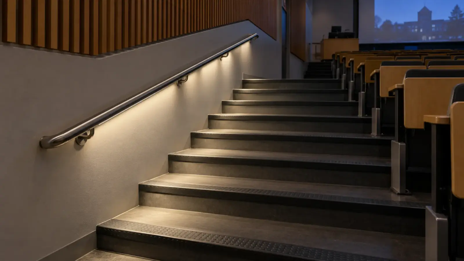
You have a 48 ft (14.6 m) corridor handrail, a 1-1/2 in (38 mm) wall clearance the ADA requires, and no place for a driver. Handrail LED strip lighting works when the slot faces the treads, the strip leaves the grip whole, the wire exits through a bracket, and the run splits into feeds a Class 2 driver can carry. A channel on the wall beside the rail has its own ADA limit; see how far a channel may stick out into a corridor.
Those are the four decisions, in the order the fabricator needs them.
The Usual Detail, and Why It Glares
The usual detail is a groove in the underside of the rail, a tape strip stuck in it, a diffuser snapped over, and the rail mounted with the groove pointing straight down. Most of the light lands on the wall and the floor against it, not on the treads. The background of a US lighting patent (9,206,953) describes the result: light aimed straight down from a handrail “throws a substantial portion of the light to the wall”.
The field fix is to rotate the rail so the groove faces the walkway. The same patent names the cost: the source comes “into a direct line-of-sight of passers-by”, a bright line at hand height for anyone walking toward the rail. TRT Lighting, a UK maker of handrail luminaires, puts the rule plainly: with low-level lighting, “visible LED points, excessive brightness or poor uniformity are immediately noticeable”.
Dark treads or a glaring line, and both come from the slot angle. Fix the angle first, then choose the strip.
Grip Rules: What the ADA Leaves Room For
A handrail is a grip before it is a luminaire, and the accessibility standard fixes the grip. The 2010 ADA Standards, section 505, read here as reproduced in California’s 2025 Building Code chapter 11B, set the numbers:
| Rule (ADA 505) | Requirement | What it means for the strip |
|---|---|---|
| 505.7.1 Circular section | Outside diameter 1-1/4 to 2 in (32–51 mm) | A slot cannot push the rail past 2 in; a 1-1/2 in tube leaves about 10 mm of wall for a groove |
| 505.7.2 Non-circular section | Perimeter 4 to 6-1/4 in, cross-section 2-1/4 in max | Flat-top rails have more room for a channel, inside the same limits |
| 505.5 Clearance | 1-1/2 in (38 mm) minimum between grip and wall | The space the brackets and the wire cross; nothing else lives there |
| 505.6 Gripping surface | Continuous; not obstructed on top or sides; bottom obstructed for no more than 20 percent of its length | The slot and its diffuser go on the underside, flush; brackets are the usual obstruction, so in our reading they count toward the 20 percent |
| 505.8 Surfaces | Free of sharp or abrasive elements, rounded edges | Diffuser edges and slot lips are rounded or flush; no exposed channel edge |
| 505.4 Height | 34–38 in (865–965 mm) to the top of the grip, consistent | The rail height sets the throw distance to the treads |
The International Building Code and ICC A117.1 carry graspability rules of the same kind; the adopted edition governs, so confirm the rail section with the AHJ before the shop drawings are stamped. For the lighting detail the reading is simple: the standard regulates the top, the sides and the bottom of the grip, and only the bottom gives you a place for light. A slot on the underside, flush diffuser, rounded lips.
Aim the Slot at the Treads, Not the Wall
Where the slot points decides whether the rail helps. In a 2019 study published in Building and Environment, Van de Perre and co-authors built a mock-up stair with an LED strip in the handrail and two strips in each nosing, aimed up and down, and had 30 elderly observers rate how safe each lighting scene felt for walking down. According to the abstract, light from the handrail or the nosing pointed downward raised perceived safety, and stronger light pointed upward reduced it substantially.
The slot therefore faces down and slightly out, toward the walkway, never up and never straight at the wall. On a round rail that means milling the groove off the bottom center, rotated 20 to 30 degrees away from the wall in our details, so the beam is centered on the treads and the slot’s outer lip shields the source from a standing viewer across the corridor. On a flat-top rail the outer lip of the underside slot sits lower than the inner lip and does the same job.
Two more choices keep the line from glaring: an opal diffuser, because a rail 36 in off the floor is seen from 6 ft away and a clear cover shows every emitter; and a continuous source, a dotless COB or dense CSP strip, because a 60 LED/m strip reads as dots at that distance.
Which Strip Fits a 1-1/2 in Rail
A 1-1/2 in (38 mm) round rail has room for a slot about 10 to 12 mm wide and 8 to 10 mm deep before the wall thickness gets thin. That rules out standard 10 mm strip in a channel and makes the narrow families the handrail families.
| Strip or channel | Width | Power | Why it suits a rail |
|---|---|---|---|
| UT-C400-3 ultra-narrow COB | 2.7/3 mm PCB | 2.1 W/ft (7 W/m), 12V or 24V | Fits a milled groove with a diffuser; cuts every 0.39 in (12V) or 0.79 in (24V); one continuous line |
| UT-C400-5 ultra-narrow COB | 4/5 mm PCB | on request | Same family, a little more width for a wider slot |
| UT-S2835-120-UN ultra-narrow SMD | 4/5 mm PCB | 2.9 W/ft (9.6 W/m) | Where a dotted line is acceptable behind a deep opal cover |
| UT-CSP-320-N | 8 × 1.85 mm | 3.05 W/ft (10 W/m) | Flat-top and rectangular rails with a wider underside channel |
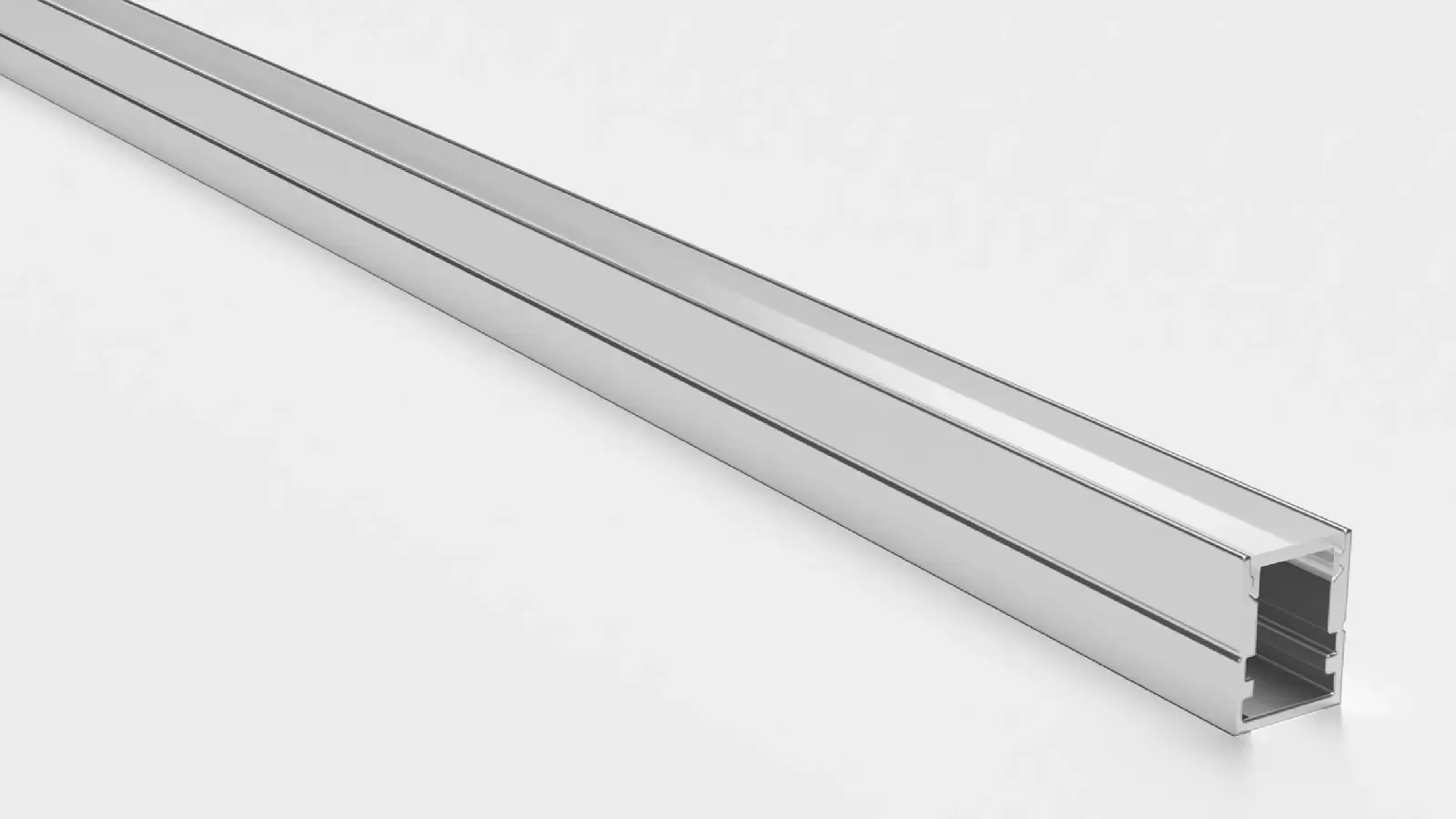
| UT-CH1207 surface channel | 12 × 7 mm, max strip 8 mm | holds the strip | Drops into a routed rectangular slot and carries the diffuser; PC clear or opal |
Runs are set by the strip, not the rail. UT-C400-3 takes 16 ft (5 m) per feed at either voltage; a longer rail gets a feed every 16 ft, which the next section plans around the brackets. Our ultra-narrow COB LED strip page lists the whole family and its cut points, and the LED channel range lists the UT-CH1207 for rails that are routed rather than milled.
Where the Wire Exits
The wire leaves the rail at a bracket. Everything else is a compromise: a lead out of the end cap, a hole in the rail face, a cord down the wall. Handrail makers’ installation guides agree on the method, a hollow wall bracket or a saddle adapter that passes the wiring from inside the rail into the wall at the bracket or return.
That makes the bracket layout an electrical drawing. The feed bracket sits at the end of each 16 ft (5 m) segment, and the wall box behind it has to be roughed in before the drywall closes, at that bracket’s exact height and offset. An installer on a German building forum described the problem every installer meets: the wall outlets have to be planned to the exact bracket position. Dimension the feed brackets on the rail shop drawings and on the electrical rough-in sheet with the same numbers.
Inside the rail, the wiring method follows the power source. An electrical contractor’s reply on the Mike Holt forum sums up the rule: if the source is marked Class 2 or Class 3, individual conductors such as THWN in the rail’s steel chase are fine; if it is unmarked or Class 1, a Chapter 3 wiring method such as conduit, AC or MC is needed in the chase. Keep the supply Class 2, mark it on the drawings, and the rail stays a low-voltage raceway. Our Class 2 driver guide covers what the inspector reads on the label.
Three details on the bench: pull the strip through the rail by its leader wires, not by the strip; seal the cut end of any IP-rated strip before it goes in, as our cut end sealing guide shows; and leave a service loop in the wall box so the rail can come off its brackets for a strip change without cutting a splice.
Feeds and Drivers for a Long Rail
A corridor handrail is long and thin, and that is the voltage drop case. At 24V the UT-C400-3 loads 2.1 W/ft and takes 16 ft per feed; the table below plans the common lengths with our 60 W Class 2 drivers loaded to no more than 80 percent, the rule on our power supply sizing guide.
| Handrail length | Load at 2.1 W/ft | Feed points (16 ft max) | 60 W Class 2 drivers at ≤80% (48 W each) |
|---|---|---|---|
| 16 ft (4.9 m) | 34 W | 1 | 1 |
| 24 ft (7.3 m) | 50 W | 2 | 2 (one driver would run at 84%) |
| 32 ft (9.8 m) | 67 W | 2 | 2 |
| 48 ft (14.6 m) | 101 W | 3 | 3 |
| 65 ft (19.8 m) | 137 W | 5 | 3 |
The 48 ft corridor from the opening needs three feed brackets and three drivers, or two if the designer accepts a larger non-Class 2 supply and the wiring method that comes with it. Each Class 2 driver, such as the UT-D60-24-C2 or the 0-10V UT-D60-24-C2-010, feeds its own segment on its own output circuit; outputs are never paralleled. The feed wire from driver to bracket carries the drop, so size it from the distance table for the actual watts and distance, and round the distance up.
Drivers go where someone can reach them: a closet, an electrical room, an accessible ceiling near the rail, never behind a finished wall at the bracket. One closet can feed the rails on both walls of a corridor if the feed runs stay inside the table. Dimming matters more here than in a cove, because a handrail is on all night in a hospital or a senior community; our white COB strip dims below 1 percent with a compatible driver, so a 0-10V channel on the nurse-station control gives a night level without switching the rail off.
Exterior Ramps and Wet Locations
An accessible ramp at a hospital entrance or a school’s drop-off has the same rail, outdoors. Rain runs along the underside of a round rail and into the slot, so the exterior version needs a sealed strip, drainage at the slot ends, and a wet-rated driver. Our IP67 extrusion-sleeve COB strip, the UT-O320-8-67 at 3.0 W/ft on 24V, fits a wider routed slot in an aluminum rail and takes 16 ft per feed; we confirm the wet location marking for the model you specify at quote, because the IP code and the marking are different things, as our wet location guide explains.
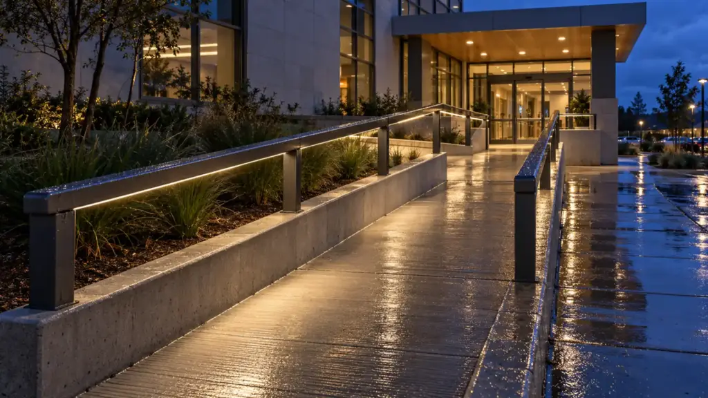
A potted IP67 driver such as the UT-D100-24-67 lives in a weatherproof box at the ramp’s base or in the building wall, with the feed entering the rail through a gasketed bracket. Leave the slot open at its low end so water drains instead of pooling against the strip, and plan on cleaning the diffuser where road salt reaches it. The outdoor and waterproof LED strip range covers the IP65 to IP68 constructions.
Hospitals, Senior Living and Hotels
The detail earns its cost where people hold the rail at night. A hospital corridor runs around the clock, and a lit handrail at 36 in gives a low, steady line a patient on foot can follow at 3 a.m. without the ceiling fixtures at full output. A senior living corridor is the clearest case: aging eyes adapt slowly and dislike glare, and the rail is the one surface residents touch; our senior living guide places it in the night path. Hotel feature stairs use the same detail for appearance, under the same grip rules.
Two limits belong on the drawings. A lit handrail is not emergency lighting unless it is on the emergency system and designed into the egress calculation; healthcare handrail manufacturers say the same of their own products, and our stair egress guide explains when strip counts. And a hospital rail is wiped with disinfectant daily, so ask the facility which agents it uses before the diffuser material is chosen.
Final Checks
- Slot on the underside, rotated 20 to 30 degrees toward the walkway, opal diffuser flush; nothing on the top or sides of the grip.
- Rail section still inside ADA 505 after the slot; 1-1/2 in wall clearance kept.
- Strip 3 to 5 mm PCB in a milled groove, 8 mm in a routed channel; dotless or dense.
- Feed brackets dimensioned the same on the rail shop drawings and the electrical rough-in; a service loop in each box.
- One Class 2 driver per 16 ft segment at 80 percent loading, reachable; wire gauge from the distance table.
- Exterior: IP67 strip, sealed cut ends, drained slot, IP67 driver, wet location marking confirmed.
- Night dimming on the control system; not counted as egress lighting unless the engineer designs it in.
The ultra-narrow strip and channels described here are in our COB LED strip and channel ranges; send the rail section and the corridor lengths with your quote request and we will mark the feed brackets for you.