

To measure foot-candles on site, use a cosine-corrected illuminance meter, hold its sensor flat at the plane the design value names (the floor for egress, desk height for work areas), keep your shadow off it, take a lights-off reading at the same point and subtract it, and average a set of points. One foot-candle is about 10.76 Illuminance on a surface: lux is lumens per square meter, footcandle is lumens per square foot, and one footcandle is about 10.8 lux. Strip ratings in lm/ft say nothing about lux until the geometry is known..
The rest is making the readings comparable with the number you are checking. Setting the target in the first place, and working back from it to lumens per foot of strip, is in our lumens per foot guide; stairs have their own points, covered in our stair lighting code article.
Foot-Candles and Lux: One Conversion, Two Units
A foot-candle is one lumen per square foot; a lux is one lumen per square meter. NIST’s conversion factor is 1 fc = 10.764 lux, so a lux reading divided by 10.764 is the same reading in foot-candles. Most meters switch between the two with a button, so measure in the unit the design document uses and convert only the summary.
| Foot-candles | Lux | Where the number comes up |
|---|---|---|
| 0.1 | 1.1 | Emergency egress minimum at any point |
| 1 | 10.8 | Egress under normal power, emergency average |
| 5 | 54 | Construction-phase corridors (OSHA) |
| 10 | 108 | Stairs in use (IBC) |
| 30 | 323 | Construction-phase offices (OSHA) |
| 50 | 538 | A conversion check, not a code number |
The code rows are quoted with their sections further down. Lux is rounded to one decimal below 20 and to whole numbers above.
The Meter: What to Check Before You Trust It
An illuminance meter is a photocell behind a white diffuser. Three things on its spec sheet decide whether the number means anything:
- Cosine correction. Light arriving at a low angle, from a cove across the room or a window, must count less, in proportion to the cosine of its angle. A sensor without good cosine correction overreads or underreads side light.
- Spectral correction. The cell has to respond like the eye, the V(λ) curve that NIST’s standard photometers are built to match. A poorly corrected cell misreads LED spectra, which differ from the lamps older meters were tuned on.
- Class and calibration. Instrument-grade meters state a class under JIS C 1609-1 or DIN 5032-7 on the spec sheet, and carry a calibration date. Use one inside its calibration interval for anything that goes into a report.
Two practical limits matter on strip jobs. Low light: the emergency minimum of 0.1 fc is about 1 lux, and the end-of-duration minimum is 0.06 fc. One maker rates its standard sensor head down to 0.01 lux but warns that its small waterproof heads may be unstable below 1 lux, so check the low end of your meter’s stated range, use one that resolves 0.01 fc, and read it on the low range. And dimming: a strip on a PWM driver usually flickers faster than the eye sees, and some meters handle that better than others; the spec sheet may say whether PWM sources are supported, and if not, ask the maker. Phone sensors are not specified for cosine or spectral response, or calibrated to a meter class, so keep phone apps for a quick comparison between two spots, not for a reading you will sign.
Where to Hold It: Plane, Height and Your Shadow
A foot-candle value always belongs to a surface. Before the first reading, find out which one the design value uses:
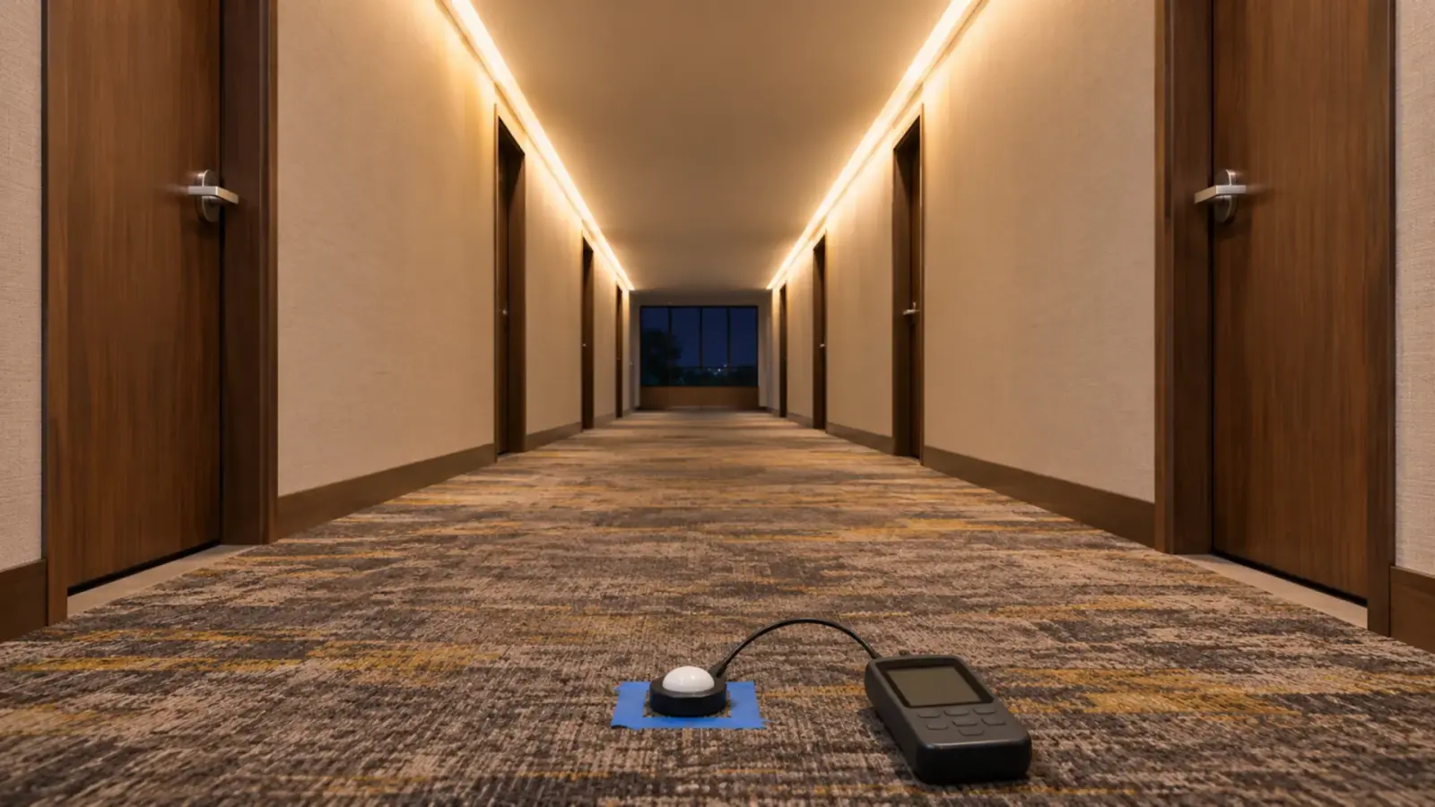
- Horizontal at the floor for corridors, lobbies and egress paths. The building code measures egress light at the walking surface under normal power and at floor level along the egress path under emergency power.
- Horizontal at desk or counter height for offices, classrooms, reception counters and kitchens. Use the height the photometric plan states; plans often use 30 in for desks, and counters sit higher.
- Vertical for walls, shelving and faces. Hold the sensor upright, facing the way the surface faces.
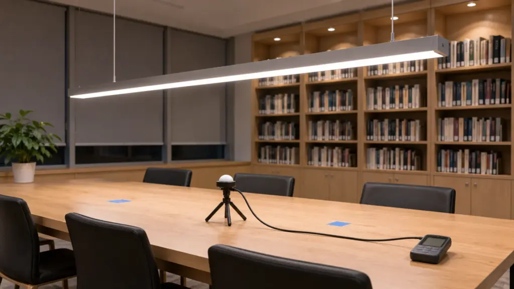
Your body is often the biggest error source. Hold the meter at arm’s length or on a stand, stay low and to the side away from the main source, and wear dark clothing if you can; a white shirt can reflect light back onto the sensor. Let the system run until the readings stop changing before you record anything (LED strip usually drops a little as it warms), the same idea an LM-79 report applies when it stabilizes a strip before measuring.
Subtract the Daylight: Lights-On, Lights-Off
A meter cannot tell your strip from the window, the corridor next door or the exit sign. To isolate the system you are checking, take two readings at each point:
- Lights on, with the controls at the scene being checked (usually full output).
- Lights off for the system under test, everything else unchanged.
The difference is what your lighting contributes. Do both readings back to back, because daylight changes by the minute. The cleanest survey is after dark or with shades closed; when that is impossible, note the time and the sky. For an egress check under normal power, the code sets a level at the walking surface without naming the source, and the level has to hold whenever the space is occupied, after dark included. Check the electric light alone, record both numbers and say which one you are comparing.
A Point Layout That Matches the Calculation
The design value on a photometric plan is calculated at points on a grid at a stated height. Measure at the same points and the comparison is one to one; measure anywhere else and you are comparing different things. Ask the designer for the calculation points, or mark them from the plan with tape before the survey.
When there is no plan, a simple layout still makes readings repeatable:
| Space | Plane and height | Points | Compare with |
|---|---|---|---|
| Corridor | Floor | Along the centerline at even spacing, plus both ends | Egress minimum and the design average |
| Stair | Treads and landings | As our stair code article lists | 10 fc in use (IBC) |
| Lobby or open area | Floor, or desk height at seating | A regular grid across the walking area | Design average and minimum |
| Office, meeting room, classroom | Desk height | A grid over the desks, not the walls | Design average at the work plane |
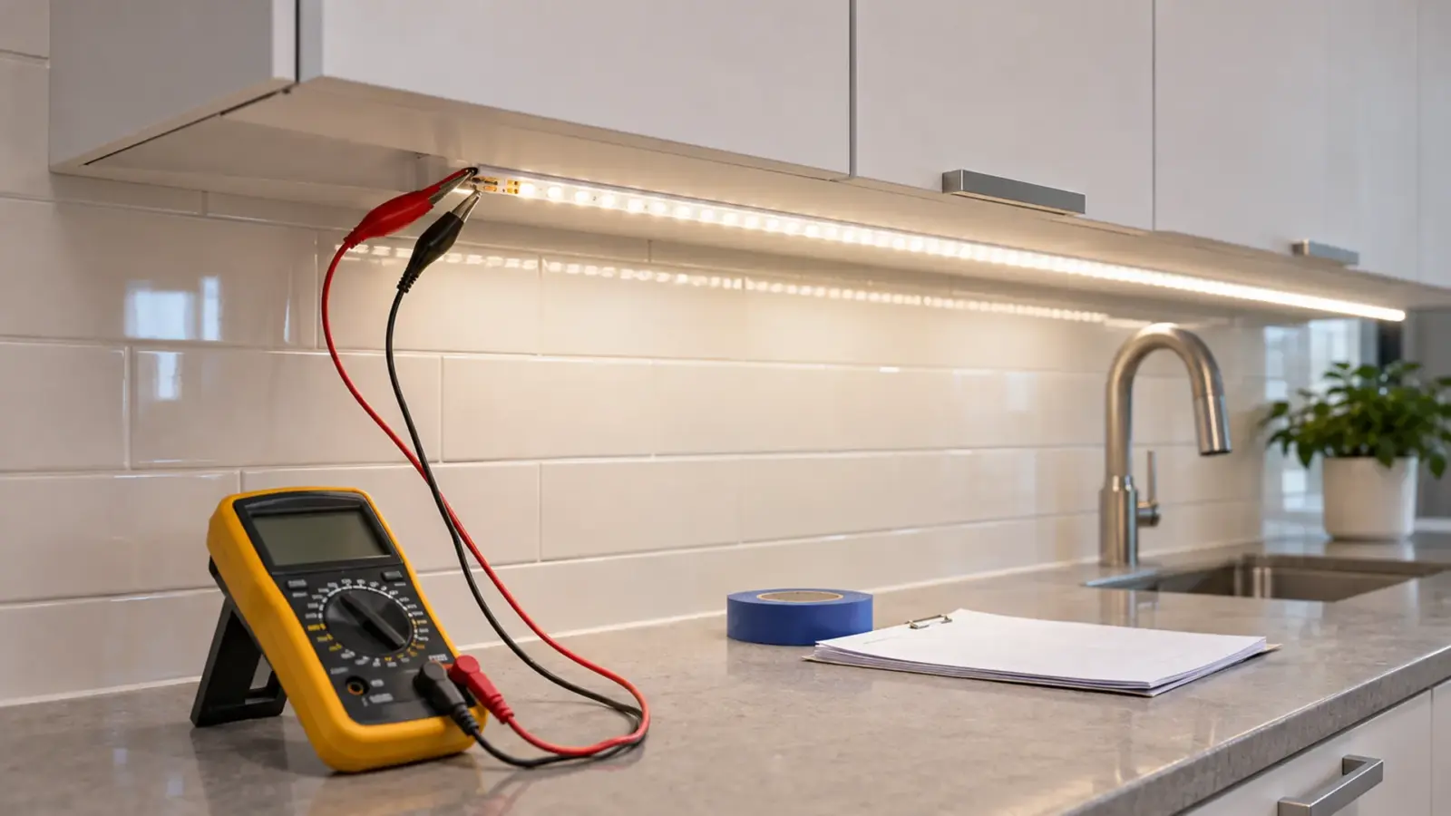
| Under-cabinet or counter | Counter top | Front edge and back edge, center of each run | Mockup reading |
| Cove | The task plane below, not the ceiling | As the space it lights | The space’s design value |
A Strip hidden on a ledge or in a recess that lights the ceiling indirectly. The cove's depth and lip height decide the throw and whether the strip is seen. is the case that catches people out. The strip sits in the cove, but the number that matters is on the floor or desk below it. Measuring at the cove lip tells you about the strip, not the room.
Reading the Results Against the Code
From the points, work out the average, the minimum and the maximum, and the two ratios designers use: average to minimum, and maximum to minimum. Then compare like with like.
The 2024 International Building Code, as adopted and published on UpCodes, sets the egress numbers. Section 1008.2.1 requires at least 1 footcandle (11 lux) at the walking surface under normal power, and at least 10 footcandles (108 lux) along exit access stairways, exit stairways and their landings when the stairway is in use. Section 1008.3.2 sets emergency lighting at an initial average of 1 footcandle and a minimum of 0.1 footcandle at any point along the path of egress at floor level, allowed to decline to 0.6 and 0.06 by the end of the emergency duration, with a maximum-to-minimum ratio no higher than 40 to 1; the 2015–2021 editions number that section 1008.3.5. The edition your jurisdiction adopted governs.
During construction, OSHA’s rule for construction sites, 29 CFR 1926.56, sets minimums while work is in progress: 5 foot-candles for indoor corridors, hallways and exitways, 10 for mechanical and electrical equipment rooms, and 30 for offices. That matters when the permanent strip doubles as work light before handover.
If the plan’s values are maintained values, which include a light loss factor, a new installation should read at or above them. A reading clearly below points to the meter, the points, the height, daylight changing between the two readings, or the installation, in that order.
Record What You Measured
Write down the meter model and calibration date, the plane and height, the point locations, the time, the lights-on and lights-off readings, and the control scene. Add a photo of the meter at a typical point. Those are the readings our commissioning and handover checklist asks you to repeat at the mockup points. If the result is short of the target, the lumens calculator compares the total output of a higher-output strip or an added run; the effect at the meter still needs the designer’s photometric run.
FAQ
How do you measure foot-candles?
Use a cosine-corrected illuminance meter set to foot-candles. Hold the sensor flat at the surface the target refers to, the floor (or the treads on a stair) for corridors and egress or desk height for work areas, keep your shadow off it, and read at several points. Take a lights-off reading at each point and subtract it to remove daylight, then average the results.
How many lux is one foot-candle?
One foot-candle is about 10.76 lux. NIST gives the factor as 10.764. To convert lux to foot-candles, divide by 10.764: 100 lux is about 9.3 fc, 300 lux about 28 fc and 500 lux about 46 fc.
What height should foot-candles be measured at?
At the height the design value or the code names. Egress light under the building code is measured at the walking surface, so the meter goes on the floor. Work areas are measured at desk height, often 30 in, or at counter height, and walls and shelving vertically. Check the photometric plan for the calculation height.
Can I measure foot-candles with a phone app?
Not for a reading you will report. Phone sensors are not specified for cosine or spectral response, or calibrated to a meter class, the way an illuminance meter is. An app can compare two spots in the same room. For code checks, Setting and verifying the controls after installation: addresses, dimming ranges, scenes and schedules, then documenting them for handover. and punch lists, use a calibrated meter that also resolves low levels such as 0.1 fc.
Why is my reading lower than the design value?
Check the measurement first: the meter’s calibration, whether you measured at the same points and height as the calculation, your shadow on the sensor, and whether the design value is the average or the minimum. Then check the installation: controls not at full, dimmed scenes, failed sections, or a lower-output strip than specified.
Spec Notes for Field Readings
Put the measurement method in the specification, not only the target: the plane and height, the calculation points to be used, lights-off subtraction, the control scene, and the meter’s calibration. With those written down, the contractor, the commissioning agent and the owner measure the same thing. Strip output for each model is listed on our SMD LED strip spec tables.