

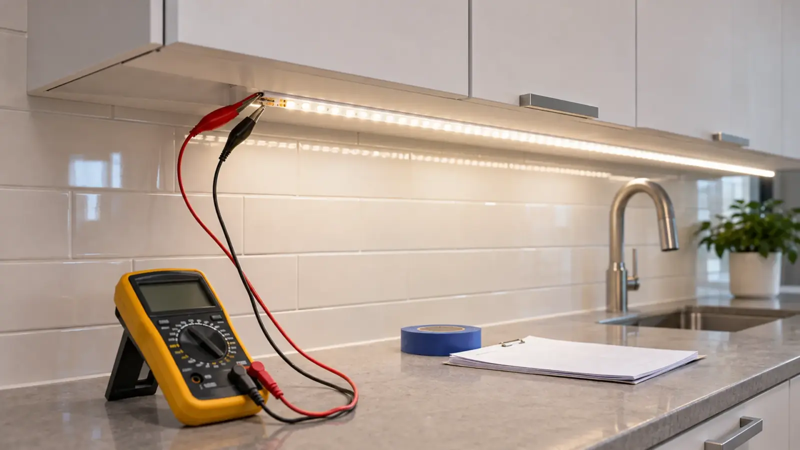
To test LED strip with a multimeter, read DC volts at the The power supply that turns line voltage into the DC the strip needs, and carries the dimming interface. Also called a power supply or transformer, though it is not a transformer. output and again at the strip’s feed pads with the run connected, then switch the power off and use continuity to find opens and shorts. Skip diode mode on a 12V or 24V run: a good segment reads OL, the same as a dead one.
This page covers the meter itself: the dial setting, where the probes go, and what each number tells you. The order for chasing a fault from the driver out to the far end is in our LED strip troubleshooting guide. Use the two together on a punch-list visit or an acceptance check.
Meter Setup: Jacks, Dial and Probe Tips
- Jacks. Black in COM, red in V/Ω. A red lead left in the amps jack and touched across a driver output shorts the supply through the meter: a Class 2 driver trips into protection, a larger supply can blow the meter’s fuse.
- Dial. DC volts, on a range above the system voltage.
- Prove the meter. Read a source you know is live before you trust a zero; a loose lead reads 0 V on a good driver.
- Probe points. Bare copper only: cut-point pads, a connector terminal, or the feed wire. On IP65 and IP67 strip, read at the feed lead or a connector instead of stabbing the silicone and breaking the seal.
- Write it down. Every reading gets a location and a time.
DC Volts: Driver First, Then the Feed Pads
Two DC readings answer most questions on 12V and 24V runs. Take both with the strip connected and lit: a driver can show full voltage unloaded and sag under load.
- Driver output terminals. Red on V+, black on V−: what the driver delivers under load.
- Feed pads on the strip. Red on +, black on −, at the first cut point. The difference from reading 1 is what the feed wire and its terminals cost.
On a long run, add a third reading at the last cut point; the gap from the feed pads is the drop along the strip. Our voltage drop guide explains the math, and the voltage drop calculator shows what a wire size and length should cost. Compare the run with its rated length on the spec sheet: our 24V SMD LED strip such as UT-S2835-60 is rated 16 ft (5 m) per feed, and UT-C312-8 COB 32 ft (10 m) with no voltage drop.
Two details change the number without anything being wrong:
- Dimmed output. A PWM dimmer switches the output on and off very fast, and a DC meter shows something close to the average, so a run dimmed to half reads well under 24 V. Read at full.
- RGB and tunable white. Read each channel against the common with only that channel at full.
What Each Reading Means
For a 24V system read under load. The driver datasheet sets the output tolerance.
| Reading | What it usually means | Next move |
|---|---|---|
| 0 V at the driver output, loaded and unloaded | No input, driver in protection, or failed driver | Read AC at the driver input; see driver troubleshooting |
| Normal with the strip unplugged, collapses when connected | Overload or a short on the load side | Power off and run the short check below |
| Normal at the driver, clearly lower at the feed pads | Resistance in the feed: wire too small or too long, a loose terminal | Check the gauge and length with the calculator; re-terminate |
| Normal at the feed pads, lower at the far end, run within its rating | A poor joint or pad along the run | Read across each joint; the bad one shows its own step |
| Lower at the far end on a run longer than its rating | Voltage drop by design | Add a feed or a center feed |
| A minus sign in front of the number | Polarity reversed between meter and pads, or wires swapped | If the leads are on the marked pads, the wires are landed backward |
| Changes as someone moves the dimmer | PWM averaging, not a fault | Read at full output |
| Voltage on both sides of a dark section | A failed LED group in that section | Cut it out at the marked cut points |
| A few volts with the switch off | Leakage from a dimmer or lit switch | See LED tape that glows when off |
| Steady voltage while the strip visibly flickers | Driver and dimmer pairing, heat or overload | See LED strip flicker |
The minus sign deserves a second look. A −24.0 reading with the red lead on the pad marked + says the feed is reversed before anyone opens a connector, and single-color strip will not light reversed.
Continuity and Shorts With the Power Off
Continuity mode asks one question: is there a path? Fluke’s continuity guide has the circuit de-energized first; the meter beeps when it finds a complete path.
Short check before first power-up. Driver disconnected, one probe on the + feed pad, one on −. A healthy run does not beep: the LED groups need far more voltage to conduct than the test supplies. A beep or near 0 Ω is a short, usually a staple or screw through the strip, a crushed section, a solder bridge or crossed connector pins. Open the run at a middle joint, test each half, and keep halving.
Open check along the run. + pad at the feed end to + pad at the far cut point should beep; repeat on −. No beep means a cracked trace, a lifted pad or an open joint. Walk the far probe back one joint at a time.
Feed wire check. With both ends disconnected, twist the conductors together at one end and expect a beep at the other; untwist and expect silence.
On addressable strip, disconnect the controller. A reading that starts low and climbs is the capacitors charging; only a reading that stays near zero is a short.
Diode Mode: One LED Yes, a 12V Segment No
Diode mode is the test most videos show, and it misleads on strip. According to Fluke, the diode test puts a small voltage across the part and displays the forward drop, and it shows OL when the part is reversed or open. The ceiling is low: the Fluke 117’s diode range reads up to 2 V and the 87V’s up to 3 V, and the test supplies only a few volts.
Now look at what sits between two cut points. UT-S2835-60 carries 60 LEDs per meter and cuts every 1.97 in (50 mm) at 12V, so each 12V group is three LEDs in series. The 24V version cuts every 3.94 in (100 mm), so each group is six. A white 2835 LED drops about 2.8 V at its rated current (Samsung’s LM281B+ is listed at 2.8 V at 65 mA). Three of them drop about 8.4 V at rated current, six about 16.8 V. A test that supplies a few volts cannot push current through the group, so a good segment reads OL, and so does a dead one.
Where diode mode does help:
- One LED, after volts have found the bad group. Power off, red on the LED’s anode, black on its cathode. A good LED reads its forward drop and may glow faintly; a failed one reads OL. A Fluke field note from a scoreboard repair shows the method: about 1.6 V and a slight glow on the working LEDs (the color is not stated), OL on the failed one. A white LED drops more than 2 V, so on a meter whose diode range stops at 2 V a good white LED can read OL too; know your meter before you condemn a part.
- Not on COB. COB covers its chips with one continuous phosphor line; there is no single LED to probe.
Current: Clamp the Feed, Not the 10 A Jack
A current reading tells you whether the load matches the drawings. Expected current is watts per foot times length, divided by system voltage. Sixteen feet of UT-S2835-60 at 1.5 W/ft is 24 W, which is 1.0 A at 24V. Far above that means a short or more strip than drawn; far below on a dim run points to drop or failed groups.
Compare the total with the driver as well. Our Class 2 drivers such as UT-D60-24-C2 are rated 60 W at 24V, and keeping the load at or below 80% of the rating means 48 W, or 2.0 A.
Use a clamp that reads DC amps; an AC-only clamp tells you nothing on the strip side. Clamp one feed conductor, not the pair, because the two currents run in opposite directions and cancel. Zero the DC clamp before you close it on the wire, and treat a reading around 1 A as a check, not a precise measurement.
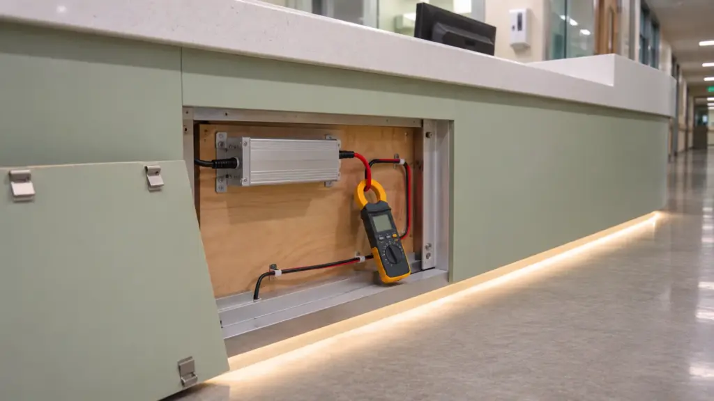
The amps jack works too, but Fluke’s 115/117 manual spells out the cost: remove power, break the circuit and put the meter in series. On a finished cove the clamp is the better tool.
120V Strip: Readings for a Qualified Electrician
120V strip such as UT-H120-60 runs direct AC through a listed rectifier plug, so the strip itself carries line voltage. Every reading at its pads is a live line-voltage reading. OSHA’s general-industry rules allow only qualified persons to perform testing work on electric circuits, 29 CFR 1910.334(c)(1), or to work on parts that have not been deenergized, 1910.333(c)(2); construction sites fall under Part 1926. Our 120V LED strip page asks for hardwired installations to be completed by a licensed electrician.
If you are not qualified for live work, check only with the circuit off and the plug out: the plug, the end caps, cuts and crush damage, and where a dark section starts and ends. On UT-H120-60 a dark section one cut interval long, 19.7 in (500 mm), is usually one group; leave the live reading to the electrician.
Accept the Reel Before It Goes Up
The cheapest time to test if an LED strip is OK is before it goes into a cove or channel. Five minutes per reel:
- Match the label to the driver. A 24V strip on a 12V driver stays dark, because six LEDs in series need more than 16 V; a 12V strip on a 24V driver is overdriven and can be damaged.
- Run the short check across + and − at the reel’s lead before power.
- Power it from the specified driver and read DC volts at the lead under load.
- Walk the reel and look for dark groups and color that differs from the label.
- Record the reel label, the readings and the date.
Those records shorten any warranty conversation. The readings to hand over at completion are in our commissioning and handover checklist.
FAQ
Can you test an LED strip with a multimeter without power?
Partly. With the driver disconnected, continuity mode finds shorts between + and − and opens along the copper bus, and on a meter with a 3 V diode range, diode mode can check a single LED. An unpowered test cannot show whether every group lights or whether the voltage holds under load; for that, power the run and read DC volts at the driver and the feed pads.
What voltage should a 24V LED strip read?
At the feed pads, under load, close to the driver’s rated output; the driver datasheet gives its tolerance. The far end of a long run reads lower because of Voltage lost along the copper between the driver and the far end of a run, which dims the far LEDs. It grows with current and length and shrinks with higher voltage and heavier wire.. If the far end is low on a run that is within its rated length, look for a poor joint. If the run is longer than its rating, add a feed rather than a larger driver.
Why does my multimeter show OL on a good LED strip?
Diode mode reads only up to 2 or 3 V and supplies a few volts. A 12V strip segment has three LEDs in series and a 24V segment six, and each white LED drops about 2.8 V, so the meter cannot push current through the group. A good segment reads OL, the same as a dead one. Use DC volts on a powered run instead.
How do you find a short in an LED strip?
Disconnect the driver and test across the + and − feed pads in continuity mode. A beep or a reading near 0 Ω means a short. Open the run at a joint near the middle, test each half, and keep halving until the short is between two cut points. On new installs, look first for a staple or screw through the strip, a crushed section or a solder bridge.
Is it safe to test 120V LED strip with a multimeter?
Only for a qualified electrician using a meter rated for the circuit. 120V strip carries line voltage on the strip itself, and OSHA’s general-industry rules limit testing and work on parts that have not been deenergized to qualified persons. An installer who is not qualified should check the plug, end caps and strip with the power off and leave live readings to an electrician.
Spec Notes for Test Access
Testing is fast when the job is drawn for it. Put drivers where they can be reached, label each with the runs it feeds, mark feed points on the as-builts, and on sealed IP65 or IP67 runs leave a lead or connector at each feed. Record loaded driver output, feed-pad voltage, far-end voltage and feed current at handover: the baseline for the next service call.
The run limits and cut intervals behind the numbers above are in our SMD LED strip spec tables.