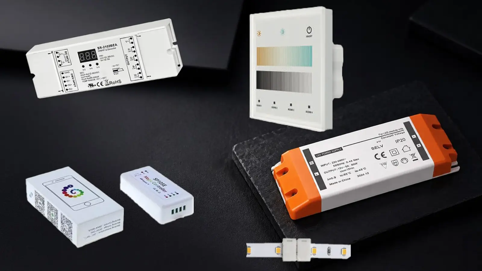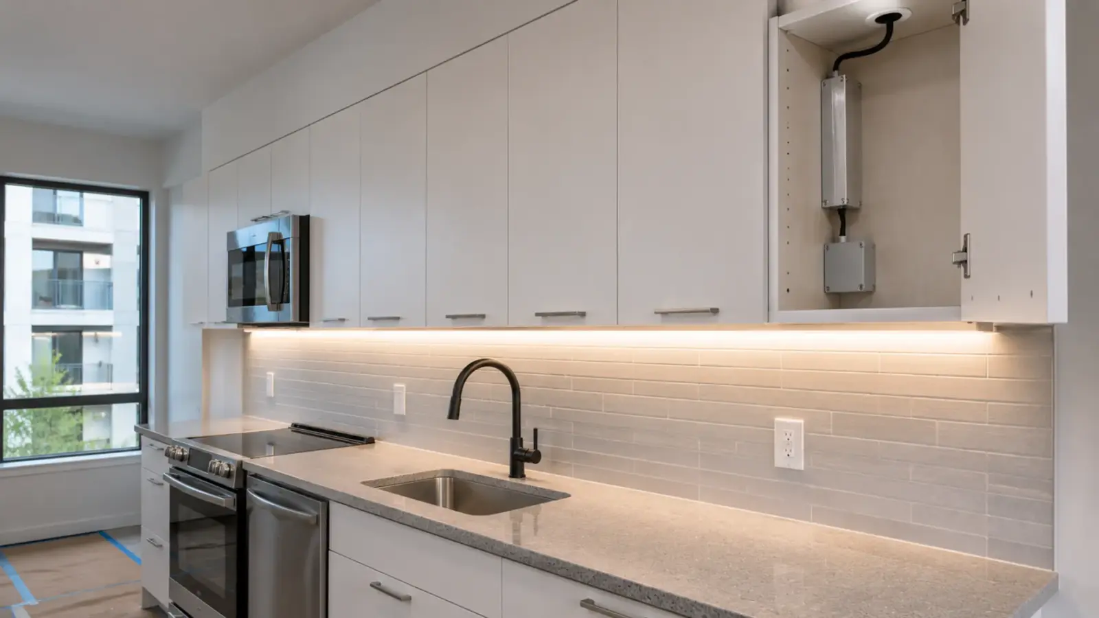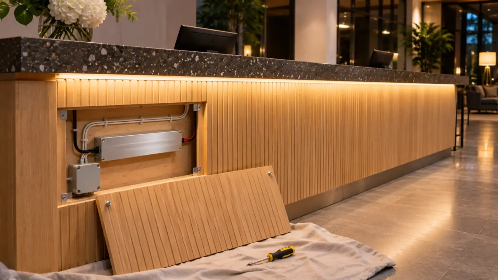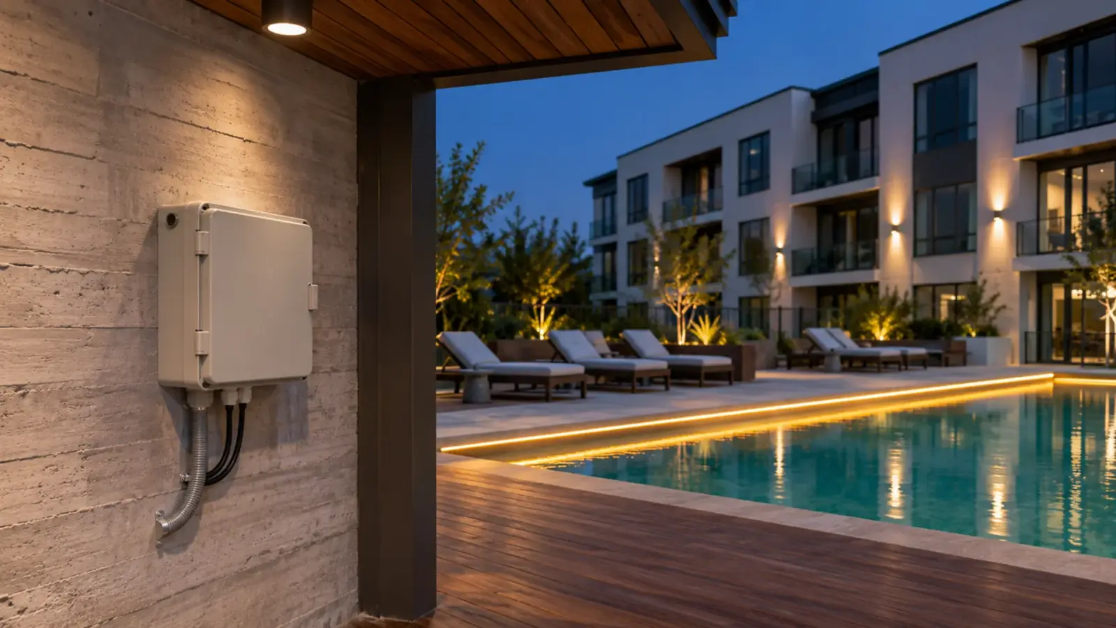


What is an LED driver, and does a 24V strip need one? An LED driver is the power unit between the building’s 120V to 277V AC circuit and the strip, and every low-voltage strip needs one. On most strip jobs it is a constant-voltage supply that holds 12V or 24V DC while the strip draws the current it needs.
The type you order comes from five answers about the job, not from the wattage alone. This page takes them in the order they rule models out.
What an LED Driver Does on a Strip Job
An LED driver does three jobs on a strip run. It turns line-voltage AC into low-voltage DC, it holds that output steady as the load and the mains change, and on a dimmed job it takes the dimming signal and turns it into lower output. The strip itself has only resistors or small current regulators on the board; it cannot be wired to a 120V branch circuit.
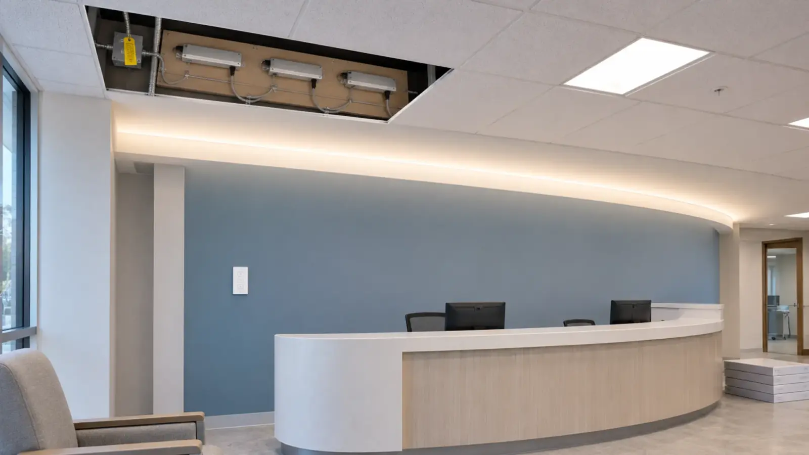
Light fixtures carry their driver inside the housing. Strip almost never does: the driver is a separate box, mounted where it can be reached, with a low-voltage cable run to the strip. That box is what this page is about.
The one strip that skips the box is 120V line-voltage strip. It connects to line voltage through a rectifier plug, with no LED driver and no 12V or 24V wiring, and a single feed runs up to 98 ft (30 m) at 120V. It has its own limits on cutting, cords and dimming, which our 120V vs 24V comparison sets side by side. Everything below is about 12V, 24V and 48V strip.
Driver, Power Supply or Transformer?
On a strip job, “driver” and “power supply” usually mean the same constant-voltage unit. Power supply is the catalog word, driver is the usual word on the listing, and the schedule may use either.
“Transformer” needs a second look. Strip sellers often use it loosely for the same DC supply, but a transformer left over from a halogen system may have a 12V AC output. 1000Bulbs makes the same split in its guide: AC drivers and transformers serve 12V AC lamps such as MR16s, and a DC-input LED cannot run on them. Strip on the schedule needs DC. Read the output line on the label: “12V AC” is not the part, even when the voltage matches.
Constant Voltage or Constant Current
The first type question decides which family of driver you are even looking at. Constant-voltage (CV) strip, printed 12V, 24V or 48V, runs on a CV driver: the driver holds the voltage and the strip takes its current. Nearly every architectural strip run is CV, and so are all 50 drivers in our driver table.
Constant-current (CC) strip and CC neon flex are the exception. They are built for long single-feed runs and need a CC driver set to the strip’s current; a CC model on a CV supply either fails to light or is damaged. Our CC strip models carry a “-CC” suffix and their drivers are matched at quote. When to choose CC strip in the first place is covered in our guide to constant-current vs constant-voltage strip.
Class 2 or Not: Why 60 W Splits a Run
A Class 2 driver is power-limited, so its output can be wired as a Class 2 circuit, which is why it is the default for interior architectural strip. The limit is low: our 24V Class 2 drivers are rated 60 W or less (40 W and 60 W), and only 3 of the 50 drivers on our page are Class 2. Above that, the job uses more drivers or a non-Class 2 driver with its output wired as a power circuit.
The limit changes the count, not only the part. A 40 ft cove of UT-C480-8 at 3.2 W/ft loads 128 W. With our practice of keeping a driver at or below 80% of its rating, a 60 W Class 2 driver carries 48 W, so the cove becomes three drivers and three secondary circuits instead of one 160 W supply. The 80% figure is our sizing rule, not a code number; the math is in the power supply sizing guide.
Class 2 also does not lift the voltage limit for the system. The 2023 NEC text of 411.3 limits low-voltage lighting systems to 30 V ac or 60 V dc, or 15 V ac or 30 V dc where wet contact is likely. What the inspector checks on the label and the wiring is in our Class 2 vs non-Class 2 guide, and the wiring method for the output is confirmed with the AHJ.
Input Voltage: The 277V Check
The next question is about the line side, and it rules out more drivers than any other. Many commercial buildings run their lighting on 277V branch circuits, and a driver labeled 100–240V does not go on one.
In our own driver table, 40 of the 50 models are 100–240V input. Six accept 277V: the three Class 2 drivers, the two linear-case drivers (UT-D150-24-L and UT-D400-24-L) and the 96 W 0-10V driver UT-D96-24-010. The potted IP67 drivers read 90–264V, and the TRIAC driver UT-D60-24-TRC is 120V only.
So before wattage, read the panel schedule. If the strip lands on a 277V lighting circuit, either the driver has to say 277V in its input range or the electrician brings a 120V circuit to that location. Choosing late is how a driver arrives that no circuit in the room can feed.
Case and Location: Where the Driver Sits
The case is chosen by where the driver will live for the next ten years. The lines in our table map to three kinds of places:
- Dry interior spaces (ceiling voids, millwork, electrical closets): IP20 enclosed drivers in slim aluminum cases. The 350 W and 400 W slim cases are fan-cooled, so they need airflow and service access.
- Inside channels and millwork: linear-case drivers, long and narrow enough to sit beside the strip.
- Damp and wet locations: IP67 potted or sealed drivers. An IP20 driver stays in a dry space, outdoors or not.

Two more things belong here. Heat: a driver’s rating assumes cooler air than it finds above a sealed ceiling, and capacitor life roughly halves for every 10°C (18°F) rise, which is why a hot ceiling often means a bigger driver. Reach: a driver someone cannot get to without opening finished work is a future service call, and moving it farther away has its own limit, set by the low-voltage cable to a remote driver.
Dimming Input: Picked With the Wall Control
The dimming input is chosen with the control, not after it. A 0-10V driver needs a 0-10V control. A TRIAC driver needs a compatible phase-cut dimmer; our 120V TRIAC driver, UT-D60-24-TRC, fits a job reusing wall-box dimmers. A driver labeled “Non-dim” ignores both.
The trap is on DALI and DMX jobs. There, the strip driver is usually a plain non-dimming CV supply, and the dimming happens in a decoder between the driver and the strip: a DALI DT8 decoder such as UT-CDALI-DT8 for tunable white, or a DMX512 decoder such as UT-CDMX-480 for color. Ordering a “dimmable driver” for that job buys a feature nobody connects. Write “non-dim CV driver plus decoder” instead. Which protocol suits which control system is in our 0-10V vs TRIAC vs DALI guide.
Efficiency: What the Percentage Costs in Heat
Efficiency on a driver label is the share of input power that reaches the strip; the rest becomes heat in the box. On a large driver in a closed space, the difference between two models is easy to put in watts.
Take 160 W of strip on a 200 W driver (80% loading). Our table lists the slim UT-D200-1224-20S at 86–88% and the high-efficiency UT-D200-1224-20H at 93.5–94%, both as the maker’s figure at full load:
| Driver (200 W, IP20) | Listed efficiency | Input for 160 W of strip | Heat in the cavity |
|---|---|---|---|
| UT-D200-1224-20S, slim case | 86–88% | about 182–186 W | about 22–26 W |
| UT-D200-1224-20H, high efficiency | 93.5–94% | about 170–171 W | about 10–11 W |
Using the full-load figure at 80% loading is an approximation; the datasheet curve for the exact model is confirmed at quote. About 11 to 16 W less heat is small in a mechanical room and noticeable in a closed millwork cavity, where it is the difference that pushes a driver into derating.
The same numbers show up on the panel. The branch circuit carries the driver’s input watts, not the strip’s, so a circuit count built from strip watts alone runs short on a job with many large drivers.
From Five Answers to an Order Line
The five answers make one line on the order. A typical tenant fit-out shows how three zones on one job end up with three different drivers.
The job is a medical office suite with 277V lighting circuits. The reception cove is 40 ft of 24V COB strip on a 0-10V wall dimmer. The entrance canopy outside has 24 ft of IP67 outdoor strip on a photocell. The break room has 12 ft under the cabinets on an existing 120V TRIAC dimmer.
| Zone | Load | Output · Class 2 · input · location · dimming | Order line |
|---|---|---|---|
| Reception cove, UT-C480-8, 3.2 W/ft | 40 ft = 128 W | CV 24V · Class 2 · 277V · dry ceiling · 0-10V | 3 × UT-D60-24-C2-010, runs of 13–14 ft, about 42–45 W each (69–75%) |
| Entrance canopy, UT-O480-10-67, 3.2 W/ft | 24 ft = 76.8 W | CV 24V · non-Class 2 · 120V circuit needed · wet · non-dim | UT-D100-24-67 at 77%, two 12 ft runs fed separately, on a 120V circuit; or UT-D150-24-L (277V) where IP65 is accepted |
| Break room under cabinet, UT-C480-8 | 12 ft = 38.4 W | CV 24V · within 60 W · 120V · dry cabinet · TRIAC | UT-D60-24-TRC at 64%, compatibility checked against the dimmer |
Both strips list 16 ft (5 m) per feed, so every run in the table is fed at 16 ft or less: the cove as three runs, the canopy as two 12 ft runs from one driver. The canopy line is the one that would have gone wrong: the wet-location driver that fits the load does not take 277V, so the circuit or the driver has to change before the order goes in.
Our drivers, controllers and connectors tables list the input range, IP rating and dimming input for every model in this example.