

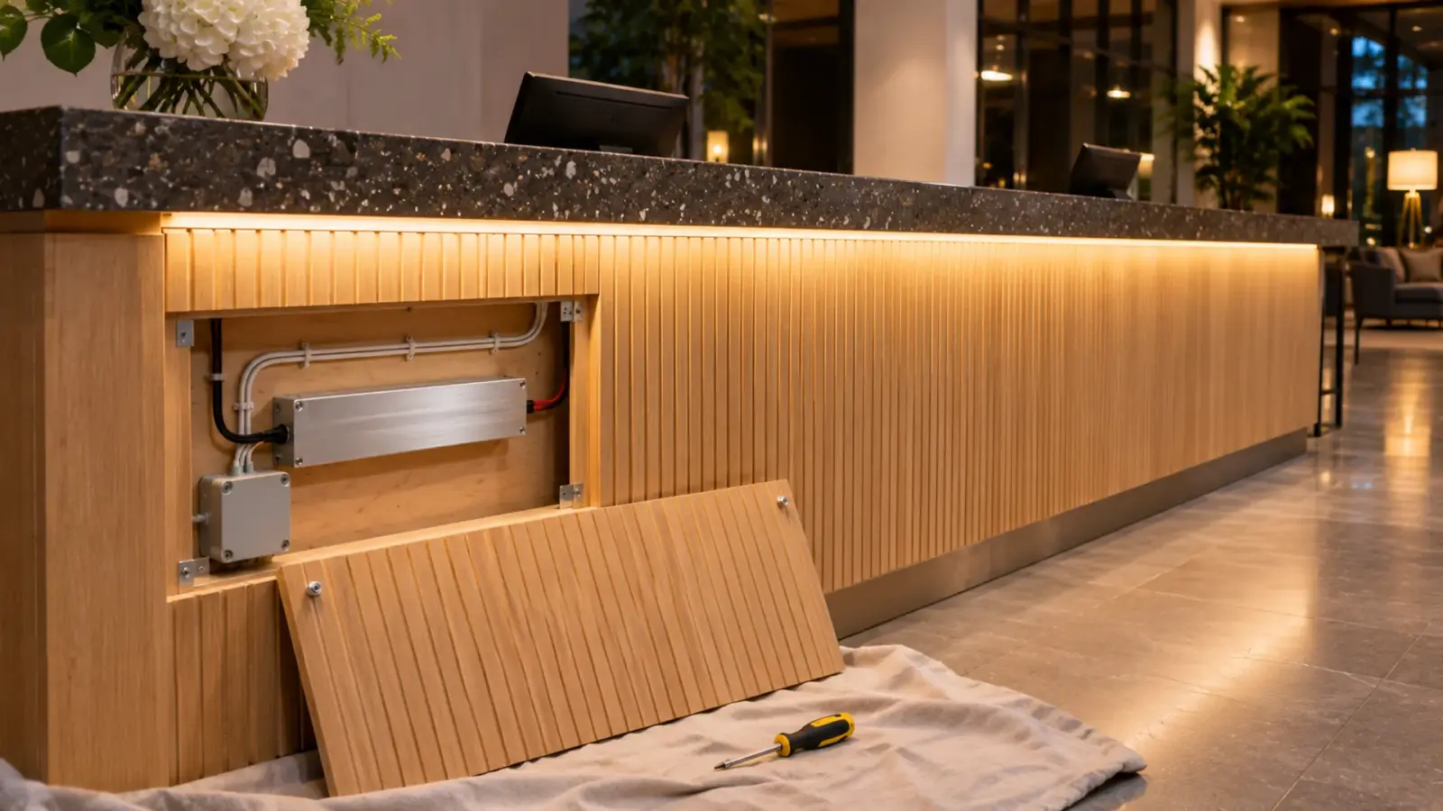
The strip line under a hotel front desk is dark, the driver behind the service panel is discontinued, and heat has baked half its label off. A replacement LED driver has to match the old output type and its voltage or current, keep its An NEC Article 725 output class limited to 100 VA at up to 60 V DC, with the wiring relief that comes with it. Our Class 2 drivers are rated 60 W; a bigger load needs more outputs or a non-Class 2 driver. status and dimming method, and carry the load with headroom.
The last section covers jobs where copying the old driver is wrong, because it, or the place it sat, is why the light went out.
Prove the Driver Is the Fault First
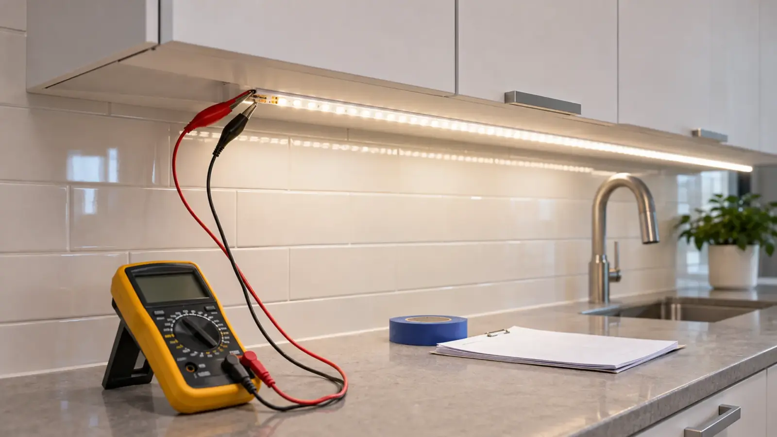
A replacement driver that was never faulty costs a second visit. Three readings settle it, input, output with no load and output with the load, as our LED driver troubleshooting guide shows; a driver that clicks on and off is usually protecting itself, as the hiccup mode guide explains.
Checkpoint: good input, no output with nothing connected, no recovery after a power cycle. Only then does the label matter.
Copy the Label: What the Replacement LED Driver Must Match
Photograph the label before the old driver comes out. Signify’s checklist for its field replacement drivers asks for nine items, from the mains voltage and dimming interface to Class 2 status and physical size. Most are lines on the label, and each has a rule:
| Label line | Must the replacement match it? | What may differ |
|---|---|---|
| Output type: CV (one voltage, such as 24V DC) or CC (a current, such as 700 mA, with a voltage range) | Yes, always | Nothing |
| Output voltage on a CV driver | Exactly: 12V, 24V or 48V | Nothing |
| Output current on a CC driver | The same current, or one the fixture or LED module maker allows | Never higher than the maker allows |
| Output voltage range on a CC driver | Must cover the load’s operating voltage | A wider range is fine |
| Rated power | CV: at least the load divided by 0.8 | A CV driver may be larger; a CC driver follows the fixture maker, and a Class P field swap stays the same or lower |
| Class 2 marking | A Class 2 driver is replaced with a Class 2 driver | A non-Class 2 driver may become Class 2 if it carries the load |
| Dimming | The same method, and the same phase for a phase dimmer | Nothing, unless the control changes too |
| Input voltage | Must cover the circuit: 120V, 277V or both | A wider input range is fine |
| Location and IP | Same or better: dry, damp or wet | IP67 may replace IP20 |
| Size, leads, mounting | Must fit the space and reach the terminals | A new location changes the 24V cable |
| Listing marks | Whatever the fixture, sign or strip instructions require | See the listing section |
Write those lines on the order before opening a catalog.
No Label, No Model Number
When the label is gone, rebuild the spec from what is still on site. For a 24V strip system, five clues usually cover it:
- The strip. Strip usually prints its voltage near the solder pads. If the print is gone, the cut pitch helps: our UT-C480-8 COB, made at 12V and 24V, cuts every 0.98 in (25 mm) at 12V and every 1.97 in (50 mm) at 24V. Check the pitch against that model’s datasheet.
- The load. Watts per foot from the strip’s datasheet times the lit length gives the load. Our power supply sizing guide shows the arithmetic and the datasheet lines that matter.
- A working twin. On repeated rooms or displays, the same driver often runs the next one. A DC-capable clamp meter reading on one output conductor, times the output voltage, gives the real load. For a constant-current fixture, Regency Supply’s guide reads the current on a working fixture of the same type.
- The wall control. A phase dimmer, a 0-10V slider with a violet and gray pair, a DALI keypad or a plain switch tells you the dimming input.
- The wiring. CL2 or CL3 cable on the 24V side, run through walls without conduit, says the job was wired as Class 2.
Checkpoint: if the output type or the dimming method is still unknown, stop and ask before ordering. Those are the two guesses that damage parts.
Constant Voltage or Constant Current
This is the line that cannot be wrong. A A driver that holds a fixed output, 12V, 24V or 48V DC, while current varies with the load. Most LED strip is constant voltage. (CV) driver holds one output voltage and the strip draws the current it needs; a constant-current (CC) driver holds one current and lets the voltage float inside a range. Most 24V tape is CV; the LED boards inside troffers, downlights and high bays usually run on CC drivers.
The trap on strip jobs is a constant-current strip that also prints a voltage. Our UT-C480-8-CC COB is listed as “24V CC” and runs 65 ft (20 m) from one feed; our UT-S2835-120-CC is “24V constant current”, 49 ft (15 m) on a single feed. Neither runs on a 24V constant-voltage supply; each needs a constant-current driver matched to the strip and the run, which we specify at quote. The CC models sit in the long-run rows of our COB LED strip table.

For the CC driver inside a fixture, three numbers carry over:
- Output current. The same mA, or a value the fixture or LED module maker allows. A higher current overdrives the LEDs, so “round up to the next wattage” does not apply here.
- Voltage window. The output range has to cover the module’s operating voltage. A wider range is fine.
- Power. Signify says a driver designated Class P may be serviced in the field without contacting the original luminaire maker, as long as the replacement is the same or lower power.
Interviewed by LightNOW, Acuity’s Daren Hatfield said a replacement need not be the same brand or model, but must be classified as suitable for field installation (UL Class P) and programmed to match the original settings. Write the programmed current on the new driver.
Size the Load: Headroom, Not a Match
On a CV driver, the wattage is the one line that may go up: a larger driver delivers only the power the strip draws. Our practice keeps the load at or below 80% of the rating, so the minimum rating is the load divided by 0.8. A replacement chosen at 100% of the measured load runs hot and becomes the next service call.
A typical job, rebuilt: the front desk from the opening has two runs of UT-C480-8 at 24V, 14 ft under the counter and 10 ft along the back shelf, and the label still shows “24V” and nothing more.
| Step | Value |
|---|---|
| Load | 24 ft × 3.2 W/ft = 76.8 W |
| Check with a clamp on a twin desk | About 3.2 A at 24V (76.8 W ÷ 24V) |
| Minimum rating for one driver | 76.8 W ÷ 0.8 = 96 W |
| Option A: one driver | UT-D100-1224-20S, 100 W, IP20, at 77% |
| Option B: two Class 2 drivers | 14 ft = 44.8 W on UT-D60-24-C2 (75%); 10 ft = 32 W on UT-D40-24-C2 (80%) |
| Feed check | Both runs inside the 16 ft (5 m) per feed of UT-C480-8 |
Both options carry the load; the wiring the first installer left decides between them. If the 24V cable was pulled as Class 2 wiring, option A no longer matches that wiring method, for the reason below.
Class 2 In, Class 2 Out
Signify’s replacement guidance puts the rule plainly: a Class 2 driver must be replaced with another Class 2 driver. The reverse can work if the Class 2 unit carries the power, current and voltage the old one did, which on strip jobs often means two drivers.
The reason is the wiring on the 24V side. A Class 2 output may feed the strip through CL2 or CL3 cable, without conduit in most occupancies; a non-Class 2 output is wired as a power circuit. Swap in a larger non-Class 2 unit to save a second box, and every foot of 24V cable downstream is now the wrong wiring method. Our Class 2 inspection guide covers what the inspector reads.
Our Class 2 drivers are rated 60 W or less per output: UT-D40-24-C2, UT-D60-24-C2 and the An analog dimming standard: a two-wire control signal from 0 to 10 volts sets the level on a compatible driver. Simple and common in commercial work; it needs a driver with a 0-10V input. UT-D60-24-C2-010. At our 80% practice, a load above 48 W splits across two drivers, each feeding its own runs. Do not tie two Class 2 outputs together onto one run unless the datasheet allows it.
Checkpoint: if “Class 2” appears on the old label or on the drawings, it goes on the order.
Dimming: Same Method, Same Low End
“Dimmable” on a label means little until the method is named. Copy it exactly:
- Phase dimming. Forward phase (TRIAC) and reverse phase (ELV) differ; the replacement must be rated for the phase the wall dimmer uses. Our UT-D60-24-TRC, at 120V input, handles both.
- 0-10V. The dimmer has to sink the control current of every driver on the pair; our drivers page figures up to 2 mA per driver, so compare the new driver’s figure when a zone is near the dimmer’s limit.
- DALI. A DALI driver is replaced with a DALI driver, then addressed and put back into its groups and scenes. Tunable white on DALI is usually a DT8 device.
- A controller downstream. If a decoder sits between driver and strip, the driver may be a plain CV unit and the dimming lives in the controller.
On a zone with several drivers, a new unit on the same protocol can still dim differently near the bottom, and it shows across a lobby. Test the new pair at the lowest level the room uses before the panel closes; our driver and dimmer compatibility test gives the steps, and the 0-10V, TRIAC and DALI guide the background.
Input Voltage and Location Rating
The input line is the quick check that still gets missed. A driver rated 100–240V does not belong on a 277V circuit; a 100–277V input, as on UT-D40-24-C2 and UT-D60-24-C2, covers both. Our sealed IP67 line is rated 100–240V and the potted UT-D100-24-67 90–264V; where IP65 is enough, the linear UT-D150-24-L takes 100–277V. On a 277V circuit, find the location answer and the input answer together.
Location: same or better. An IP20 driver stays in a dry space. A damp or wet location takes a sealed or potted unit such as UT-D100-24-67, IP67 and rated −13 to 140°F (−25 to 60°C). Above a ceiling that carries return air, our plenum ceiling guide reads NEC 300.22(C) as asking for a metal enclosure or one listed for the use. Outdoors, a driver inside an enclosure is sized for the heat in the box, which our outdoor driver enclosure guide works through.

Physical Fit: Case, Leads and Mounting
Measure the space, not only the old case: the millwork cavity, the channel, the junction box or the fixture’s driver tray, and check that the leads reach the old terminals.
Our linear UT-D150-24-L tucks into channels and millwork; a slim IP20 case such as UT-D100-1224-20S suits a ceiling void or a closet. A driver that will not fit may move, at two costs: the longer 24V cable needs a new voltage-drop check (our remote driver guide), and the new spot must be reachable without opening a finished surface.
Leave air around the case: our drivers page notes that capacitor life roughly halves for every 10°C (18°F) rise.
Listed Fixture, Listed Sign or Field-Built Strip
Who holds the listing decides the replacement.
- A listed luminaire. The driver was evaluated with the fixture. The cleanest route is the same model or one on the maker’s replacement list; Lutron says its UL Listed drivers suit direct field replacement with the same model number. UL describes its Class P program as letting luminaire makers source alternate drivers without recertifying the fixture; whether a Class P driver suits a given fixture in the field is for that fixture’s documentation and maker to say.
- A listed sign. The sign shop holds the listing, and a different supply model can take the sign outside it. That job has its own page: our LED neon sign power supply guide.
- A field-built strip system. Strip and driver carry separate listings, and the strip’s instructions often name the supply type, such as a Class 2 supply at 24V. A replacement used inside both sets of instructions is generally acceptable. Our guide to mixing strip, driver and controller brands explains the three joints, and our listing lookup guide shows how to check a driver’s marks.
For our own drivers, the wording on our drivers page holds: certification coverage varies by model, certification is held by the original manufacturing partner, and documentation and listing information are available upon request.

When Like for Like Is the Wrong Answer
A driver that died for a reason dies again in the same conditions. Read the old one and the place it sat first.
| What you find | What it points to | What the replacement changes |
|---|---|---|
| Discolored case, brittle leads, a sealed cavity | Heat | A derated or larger driver, or a cooler spot; see our hot ceiling guide |
| Measured load near or above the rating | Overload, or strip added after handover | A larger driver, or the runs split across two |
| Corrosion, water marks, an IP20 case in a damp spot | Wrong location | A sealed or potted IP67 unit, or a dry spot for the old type |
| Hum or flicker that began with a new wall dimmer | Control mismatch | A driver rated for that dimmer, or a different control |
| Several drivers dead after a storm, on long exterior feeds | Surges | Surge protection planned with the swap; see our surge protection guide |
| A CV driver on a CC strip, or the reverse | Wrong type from the start | The right type, after the strip is checked for damage |
| The second failure in a year | One of the rows above | Find which before the third driver goes in |
Final Checks Before the Swap
Before the panel goes back on, the service ticket should show the old label photo, the three readings, the load as a percentage of the new rating, the new model with its Class 2 status and dimming method, and where it sits. Run the zone through its range and compare the low end with its neighbors. Record the new model on the as-built drawings and the panel schedule.
When the old driver is unlabeled, discontinued or keeps failing, send us what is left of it: photos of the label and the space, the strip model and run lengths, and the wall control. We rebuild the spec, match a driver from our LED driver range to the load, the dimming and the location, and say so when the right answer is two drivers instead of one: request a quote.