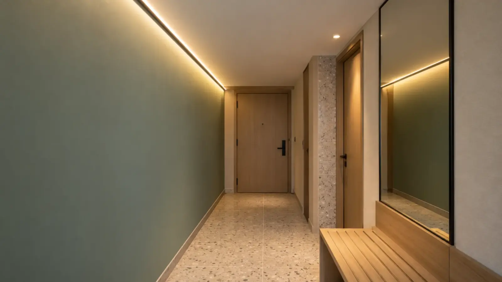
A 45 degree LED channel is an aiming device, not a corner light. The UT-CH1616 sits in a 90° inside corner and tips the strip halfway between the two surfaces, so the center of its beam lands as far out as the strip is from the surface it lights. Use it where that spot is what the job needs lit.
It loses to a flat profile in four places: where there is no true inside corner, where the strip is wider than 10 mm, where someone looks straight into the lens, and where the surface to light sits directly below the strip.
Five gates settle it for any location on a schedule, in order. A table of eight corners follows, and two diagrams show the geometry.
Gate 1: Is There a 90° Inside Corner
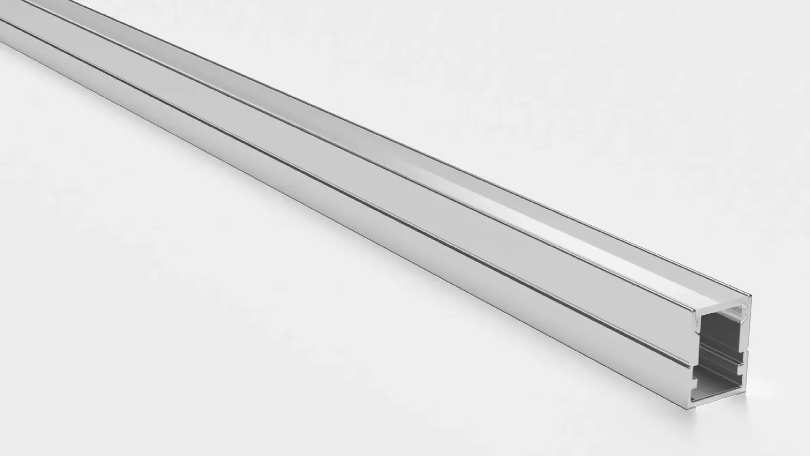
The profile needs two surfaces meeting at a right angle, with the open side facing the thing you want lit. Our UT-CH1616 corner channel has a triangular body, 16×16 mm (0.63×0.63 in), that seats into that corner, so the strip faces out along the diagonal.
Inside corners are everywhere on a commercial job once you look for them:
- the inside corner of a cove lip, where the ledge meets the lip
- the junction of a wall and a finished ceiling
- the top front corner of a display case or shelf compartment
- the underside of a stair nosing where it meets the riser
- the top of a toe kick recess, under the cabinet base
- a coffer ledge where it meets the beam face
- the ceiling edge of an elevator cab
- the back corner under a wall cabinet, where the cabinet meets the wall
No corner, no corner profile. A flat ceiling, a wall face or a shelf front takes a surface profile. An outside corner (a column edge, a counter edge) and a curve are other details, and our range has no outside-corner profile.
If the corner is out of square, the triangular body rocks. Check drywall corners with a square before ordering; a bulging corner bead or a thick caulk line can hold the profile off one face.
Gate 2: Where the Light Lands
The beam center of a strip tilted 45° travels out as far as it travels down (or up), because tan 45° is 1. A strip 18 in above a counter sends its center to the counter 18 in out from the wall. A flat profile in the same corner, aimed straight down, puts its center at the foot of the wall.
That one rule decides most locations. Here it is worked for the corners we quote most often, using typical dimensions; take the real ones from the shop drawings.
| Corner | Distance to the lit surface | 45° channel: beam center lands | Flat channel in the same corner |
|---|---|---|---|
| Under a wall cabinet, back corner, 18 in gap | 18 in down | Counter, 18 in out from the backsplash | Foot of the backsplash; much of the beam goes into the backsplash |
| Under a wall cabinet, back corner, 15 in gap | 15 in down | Counter, 15 in out | Foot of the backsplash |
| Display case, top front corner, 12 in shelf spacing | 12 in down | Shelf below, 12 in back from the front: the product faces | Front lip of the shelf below and the tops of the goods |
| Stair nosing, 7 in riser | 7 in down | Tread below, 7 in out from the riser, past the middle of an 11 in tread | Foot of the riser; it lights the riser face |
| Toe kick, 3.5 in high and 3 in deep | 3.5 in down | Floor, just past the cabinet’s front edge | Floor at the kick face, and the kick itself |
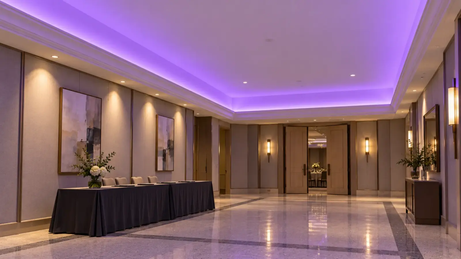
| Cove pocket, channel in the lip corner | Pocket width across, setback up | Wall-ceiling joint when the pocket is as wide as the setback; the wall below it if narrower, the ceiling short of the wall if wider | Ceiling directly above the lip, the hot band our cove page warns about |
The cove row gives a useful rule. With the channel in the inside corner of the lip, the beam center reaches the wall-ceiling joint when the pocket (lip to wall) is as wide as the setback (strip to ceiling). A narrower pocket puts the center on the wall below the joint; a wider one puts it on the ceiling short of the wall. Our cove dimensions guide sets the pocket and lip, and our cove lighting page puts the minimum setback at 4 in (100 mm).
The center is not the whole beam. Bare strip spreads wide: our CSP spec tables measure 140° to 170° for bare white strip, as our beam angle guide shows. Tilting a strip that wide does not make a spotlight. It moves the brightest part of a broad wash, and an opal cover spreads it further. That is why the tilt matters most at short distances (a kick, a nosing, a shelf) and least on a tall wall.
Under a wall cabinet the table also shows why our under cabinet guide puts a flat channel toward the front edge, behind the light rail, and our under cabinet and millwork page aims it down and slightly back. From a 12 in deep cabinet that lands its center about 12 in out. The 45° profile in the back corner lands about 6 in further out, but it brings Gate 3 into play.
Gate 3: Who Sees the Lens
The tilt that aims the light also aims the lens. A 45° profile faces out of its corner, so ask who stands in front of it.
- Under a wall cabinet, back corner. A standing adult’s eye, about 66 in above the floor, sits above a cabinet bottom at 54 in (36 in counter plus an 18 in gap), so a standing viewer does not see the lens. A person in a wheelchair, a child, or anyone looking across from a lower counter can, and the light rail at the front edge does not hide a back-corner source. A seated viewer on a stool sits close to the cabinet line; check that view on the mockup. Polished stone reflects the lit lens as a line.
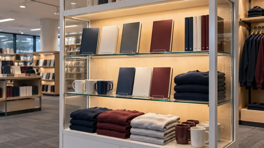
- Display case, top front corner. The lens faces back into the case and the face frame hides it. This is the profile’s best location.
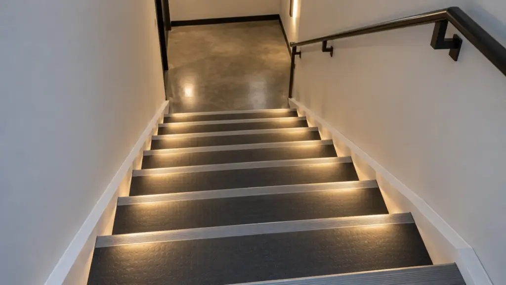
- Stair nosing. The lens faces down the stair. People going down do not see it; people coming up see a row of opal lines under the nosings. Our stairs and handrail page pairs UT-CH1616 with an opal cover there.
- Toe kick. The lens faces the floor and the cabinet edge hides it from standing height.
- Cove. The lens faces up and back. The lip hides it as long as no viewer above the ledge (a mezzanine, a landing, a balcony) can see past the lip; our cove dimensions guide works that sightline.
- Wall-ceiling junction. Everyone sees it. It is a visible linear light, and it needs an opal cover and straight, clean runs.
Where a viewer sees the lens, specify opal. Our channel page puts PC clear at roughly 90–95% transmission with the LEDs visible, and PC opal at roughly 70–80% with one continuous line; our diffuser guide covers the trade-off. Dot-free COB in an opal cover reads as one line even close up.
Gate 4: Does the Strip Fit
UT-CH1616 takes strip up to 10 mm wide. The PCB has to sit flat on the channel floor with about 1 mm of clearance, so match by the PCB width in the strip’s spec table, not by eye.
| Fits the 10 mm floor | Does not fit |
|---|---|
| UT-C480-8 dot-free COB, 8 mm, 3.2 W/ft | UT-C600D-12 dual-row COB, 12 mm |
| UT-C280-10 and UT-C1328-10 COB, 10 mm | UT-C960-15 COB, 15 mm |
| UT-SC320CRI97-15 SCOB, 10 mm, Ra≥97, 4.6 W/ft | UT-S5050-120 SMD, 12 mm |
| UT-S2835-128-HE SMD, 10 mm, 2.9 W/ft | UT-RW840-12-CSP RGBW, 12 mm |
| UT-S2835-480-FS SMD, 10 mm, Ra≥98 | UT-C1600-30 COB, 30 mm |
| UT-T120-8 tunable white, 8 mm; UT-T640-10, 10 mm | Any strip with a wider silicone coating than its PCB |
The right-hand column is the usual trap. A cove scheduled for RGBW or a high-output dual-row strip, and also for “corner channel”, cannot have both. Change the strip, or change the profile to a flat one that takes 12 mm or more, such as the 24×15 mm UT-CH2415 for 15 mm strip. Our channel selection guide has the full width table.
Heat goes the same way. A 16 mm profile is a smaller section than a 24 mm one, with less metal to spread heat, so the higher-output strips in the left column (UT-S2835-480-FS at 5.5 W/ft, UT-T640-10 at 4.9 W/ft, the SCOB at 4.6 W/ft) deserve a look. Our channel thermal guide covers when that matters.
Gate 5: Fixing and Joining
Every one of our channels ships with mounting clips and The closure at the end of a channel or neon section. On IP-rated product it is part of the seal; on channels it finishes the extrusion., and in a corner the clips are the fixing. Adhesive tape on two faces of a corner is a placement aid at best.
Some corners take abuse. A stair nosing takes feet, carts and cleaning machines, and our stairs page says to fix that channel mechanically, never with tape. A toe kick gets kicked and mopped, which also calls for a silicone-coated strip with sealed ends (toe kick guide). An elevator cab vibrates, so the profile is screwed to the ceiling frame.
Where two corner runs meet at a room corner, the profile turns but the strip may not. Miter the channel at 45° for each half of a 90° turn (how to cut aluminum channel) and plan the strip as two pieces with a jumper or connector across the turn; our cove corner guide shows how to keep that gap short.
Order length against the run schedule. UT-CH1616 comes in 6.6 ft (2 m) and 9.8 ft (3 m) lengths, in anodized silver or black, and as our LED channel range notes, we cut it to the run schedule on request so each piece arrives labeled for its location.
Job Picks: Eight Corners, One Table
| Location | Profile | Why |
|---|---|---|
| Corner cove, aimed wash | UT-CH1616 in the lip corner, UT-C480-8 dot-free COB | Aims the wash toward the wall-ceiling joint instead of a hot band above the lip |
| Wall-ceiling junction, finished ceiling | UT-CH1616, opal | A 45° aim from a 90° corner with no cut into the board (retrofit guide) |
| Display cases and open shelves | UT-CH1616 with UT-S2835-480-FS (Ra≥98) or UT-SC320CRI97-15 (Ra≥97) | Lights the product faces; the face frame hides the lens |
| Stair nosing | UT-CH1616, opal, fixed mechanically | Lights the tread below, not the eyes of people going down (stair lighting code guide) |
| Toe kick | UT-CH1616 at the top of the recess, silicone-coated IP65 strip such as UT-O320-8-65 (check its coated width at quote) | Throws light onto the floor in front, not into the back of the kick |
| Coffer ledge at the beam face | UT-CH1616 | Aims at the beam-panel joint in a shallow coffer |
| Elevator cab ceiling edge | UT-CH1616, screwed to the frame | Survives vibration; the 45° aim washes the ceiling and the upper cab walls |
| Under wall cabinets, task light | Flat UT-CH1013 toward the front edge | Hidden by the light rail from standing height; confirm seated views on the mockup |
The last row is the one exception people argue about. A 45° profile in the back corner can light a counter, but on a job with stools, wheelchair users or a polished top, the flat profile at the front is the safer answer.
Decision Rule
Specify the 45° channel where three things are true: the strip sits in a true inside corner, the surface to light is out from the corner rather than under it, and nobody looks into the lens or the lens is opal. Check the strip is 10 mm wide or less, fix the profile with its clips, and specify a flat profile everywhere else.
If your schedule mixes corner and flat profiles, send it with the millwork sections. We check each location against the strip width, the cover and the cut lengths, and return one channel list for the whole job: request a quote.