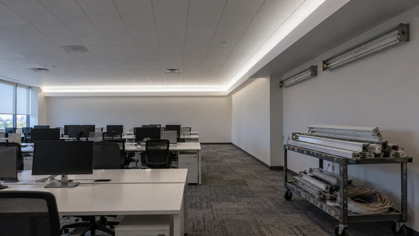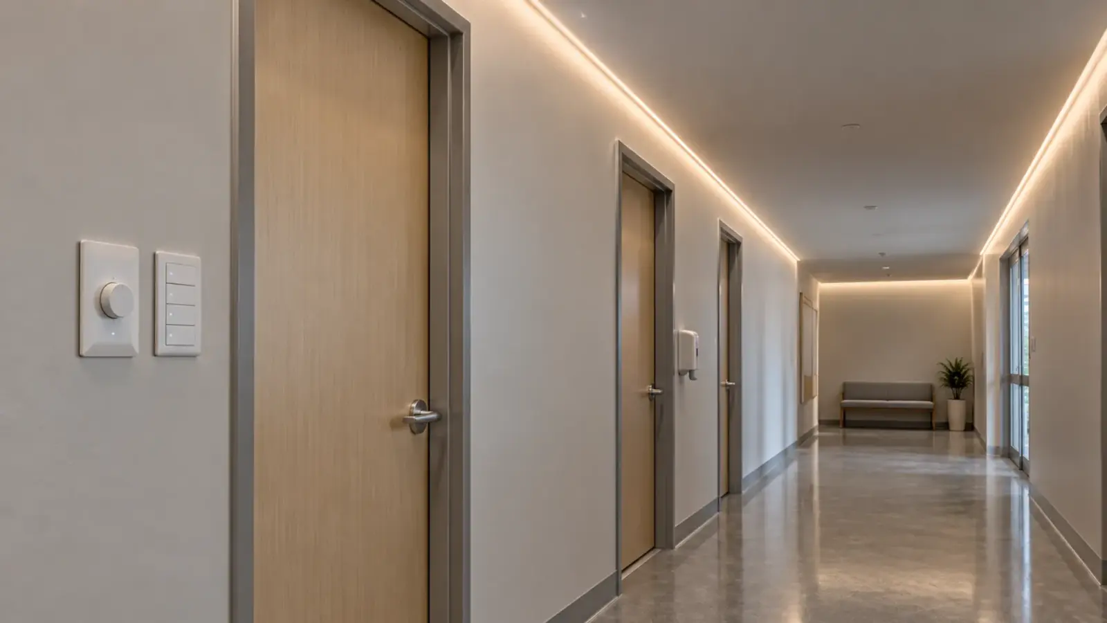
Four ways control LED strip from a wall: a line-side switch on a non-dim driver, a phase-cut dimmer with a TRIAC driver, a 0-10V dimmer with a 0-10V driver, and an RF wall panel on the low-voltage side. Pick by what the wall box carries. A licensed electrician wires the line side.
The ceiling is closed on the second floor, the wall box has a switch leg and no more, and the drawing says “LED strip, dimmable”. The answer is one of four routes, and the choice is made at rough-in, not after the drywall. This article compares them with our own drivers and controllers, and says plainly who wires what.
Before You Pick: Four Facts
Answer four questions before choosing a route.
- What is in the wall box? A switch leg, a switch and neutral, or a dimmer with a neutral. Some dimmers need a neutral at the box.
- What dimmer is already there? Reusing an existing phase-cut dimmer points to a TRIAC driver. A commercial control system points to 0-10V.
- How big is the load? Our 24V Class 2 drivers are rated at 60 W each, so a longer run splits across several drivers and circuits.
- Who wires the line side? A licensed electrician, and the AHJ sets the wiring method. We do not give code conclusions in this article.
This article covers 24V Class 2 systems. 120V LED strip is a different system: it runs from line voltage through its own supply and takes TRIAC or ELV dimming only, so it is not one of the routes below; see our guide on when to spec 120V and when to stay on 24V.
Four Ways at a Glance
| Way | Wall box carries | Driver we usually quote | Dimming | Low-voltage side |
|---|---|---|---|---|
| 1. Line-side switch | A 120V switch leg | UT-D60-24-C2 (60 W, 100–277 VAC) | None, on and off | Class 2 pair to the strip |
| 2. Phase-cut dimmer | A TRIAC dimmer, reused | UT-D60-24-TRC (60 W, 120 VAC) | TRIAC, forward or reverse phase | Class 2 pair to the strip |
| 3. 0-10V dimmer or panel | A 0-10V dimmer or wall panel plus a control pair | UT-D60-24-C2-010 (60 W) or UT-D96-24-010 (96 W) | 0-10V | Class 2 pair to the strip, plus the control pair |
| 4. RF wall panel | A switch leg or constant power; the panel is wireless | A non-dim driver plus UT-CRF-24G | 2.4G RF, up to 4 zones | Class 2 pair into the controller, then to the strip |
The models and ratings come from our drivers, controllers and connectors page. Dimmer compatibility lists ship with every quote.
Which Way for Which Space
A short table from the space to the route, as a starting point.
| Space | Usual route | Why |
|---|---|---|
| Closet, stock room, back of house | 1. Line-side switch | On and off is enough, and nothing else to maintain |
| Apartment kitchen or bedroom with an existing dimmer | 2. Phase-cut dimmer | Reuses the wall-box dimmer and the work already done |
| Office floor, corridor, any space on a building control system | 3. 0-10V | The building system sets the level and the zones |
| Retrofit with no new wire, or a renovation with closed walls | 4. RF wall panel | No new cable, and zones from a battery panel |
| Mixed building | A mix | Choose by the wall box and the control expectation, per space |
The mix is normal. A hotel uses 0-10V in corridors and phase-cut dimmers in guest rooms, and the drawings must say which is which, or the second floor gets the first floor’s answer.
Way 1: A Line-Side Switch
The simplest route. A single-pole or three-way switch breaks the line feed to a non-dim driver, and the driver feeds the strip. The switch sees only line voltage; the strip never sees the switch. It suits closets, back-of-house and any space where on and off is enough. The driver sits in a junction box, a ceiling void or a cabinet where it can be reached, as in our driver placement guide. Nothing in this route needs a compatibility test beyond the load.
Way 2: A Phase-Cut Dimmer
Where the box already has a phase-cut dimmer, a TRIAC driver reuses it. UT-D60-24-TRC dims on TRIAC, forward and reverse phase, at 120 VAC. The rest of the work is compatibility: dimmer type, minimum load, flicker at the low end. Our guides on choosing between 0-10V, TRIAC and DALI and testing driver and dimmer compatibility cover both, and the notes on Lutron dimmers show a common pairing.
Way 3: 0-10V
A 0-10V route uses a dimmable driver with two extra control wires. The dimmer or panel does not carry the load; it sends a 0 to 10 volt signal to the driver, which sets its output. UT-D60-24-C2-010 and UT-D96-24-010 take 0-10V, and our UT-CTP-010 is a 0-10V wall panel with a 100–277 VAC input, so it is a powered panel and its supply is part of the wall box wiring. This is the commercial default and works with building control systems. It adds a control pair to the wall box, which has its own wiring rules: ask the AHJ which cable class the control pair needs.
Way 4: An RF Wall Panel
Where no new wire can be pulled, a wireless route avoids it. The driver stays non-dim on the line side, and a 2.4G controller such as UT-CRF-24G sits between the driver and the strip on the low-voltage side, with a battery wall panel on the wall. It dims up to four zones. The wall panel is not hardwired; the switch leg, if there is one, only cuts power to the driver. The RF controller is a radio device, so ask for its compliance documents by model; our guide on FCC, Prop 65 and labels explains the difference between a radio device and a plain driver.
Line and Class 2 in One Box
Two circuits can share a wall box only when the code and the hardware allow it. According to the vendor sources we reviewed, some in-wall driver-dimmers include a barrier partition so high and low voltage can live in the same box, and the low-voltage wiring between the driver and the strip has to be Class 2. One maker states its strip is rated for Class 2 circuits only. Keep the line side and the Class 2 side apart, use cable rated for the location, and put the joint outside the wall where an inspector can see it.
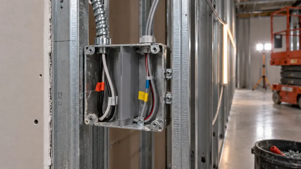
Our guide to what wire can go in the wall for LED tape covers CL2, CL3 and plenum cable, and the Class 2 driver guide covers what an inspector checks. Concealed penetrations through drywall are a common pain point, according to an installer forum; plan them at rough-in, with a box or a gland where the cable passes through.
Power and the 60 W Split
Our Class 2 drivers are rated 60 W each. At 80% loading, one driver carries 48 W. On UT-C480-8 at 3.2 W/ft that is 15 ft of strip per driver, so a 60 ft run needs four drivers, each on its own branch. Four dimmable drivers on one wall dimmer must be within its load rating, and four 0-10V drivers can share one control pair. Put the drivers together where one hatch or one closet reaches all of them, and draw that hatch on the plan, and label each with the run it feeds, so a dead branch can be traced in minutes. A 60 ft room with four drivers is four labels and four test points written on the plan, and a room with one unlabeled driver and four runs is a ceiling cut-out. The voltage drop guide and the power supply sizing guide cover the rest.
What Goes Wrong
Five faults come back often.
- A dimmer and a driver that were never tested together. The strip flickers at the low end or glows when off. Test the pair, as in the faint glow and low-end flicker guide.
- Too many drivers on one dimmer. The dimmer’s load rating is for its own load, and several drivers can exceed it. Add the loads.
- 0-10V wired with reversed polarity. The driver sees no signal or full signal. Check the pair with a meter before the wall closes.
- Line and low-voltage wire in the same raceway with no barrier. An inspector’s first question. Separate them, or use the approved method.
- A driver in a sealed box. It overheats and drops out. Keep it where it can breathe and be reached.
Test Before the Wall Closes
Before the drywall closes, wire the system as designed on the bench or in the open box: the driver, the dimmer or panel, a length of the actual strip and a load that matches the run. Dim it to the lowest level the room will use and leave it on for ten minutes. Look for flicker, glow when off and buzzing. Record the model pair and the result. Our wiring diagrams guide shows the low-voltage connections from two wires to five.
Final Checks
Before the order, confirm what the wall box carries, the route, the driver and dimmer model pair, the number of drivers for the run, the wire class for the low-voltage and control pairs, and who wires the line side. Send the plan and the control scheme and we confirm the drivers and the compatibility list at quote. If the walls are already closed, tell us which wall-box devices are installed and we start from those, because the cheapest route is the one that reuses the box that is already there.